MS300/MH300 PROFINET Communication Card CMM-PN02
CMM-PN02 Operation Manual
3.4.3 MH300 Mounting Position 2 (See Section 3.1 for Details on Mounting Position) -
Frame E and F
Installation method: Front-mount the communication card by connecting flat cables to
the control board.
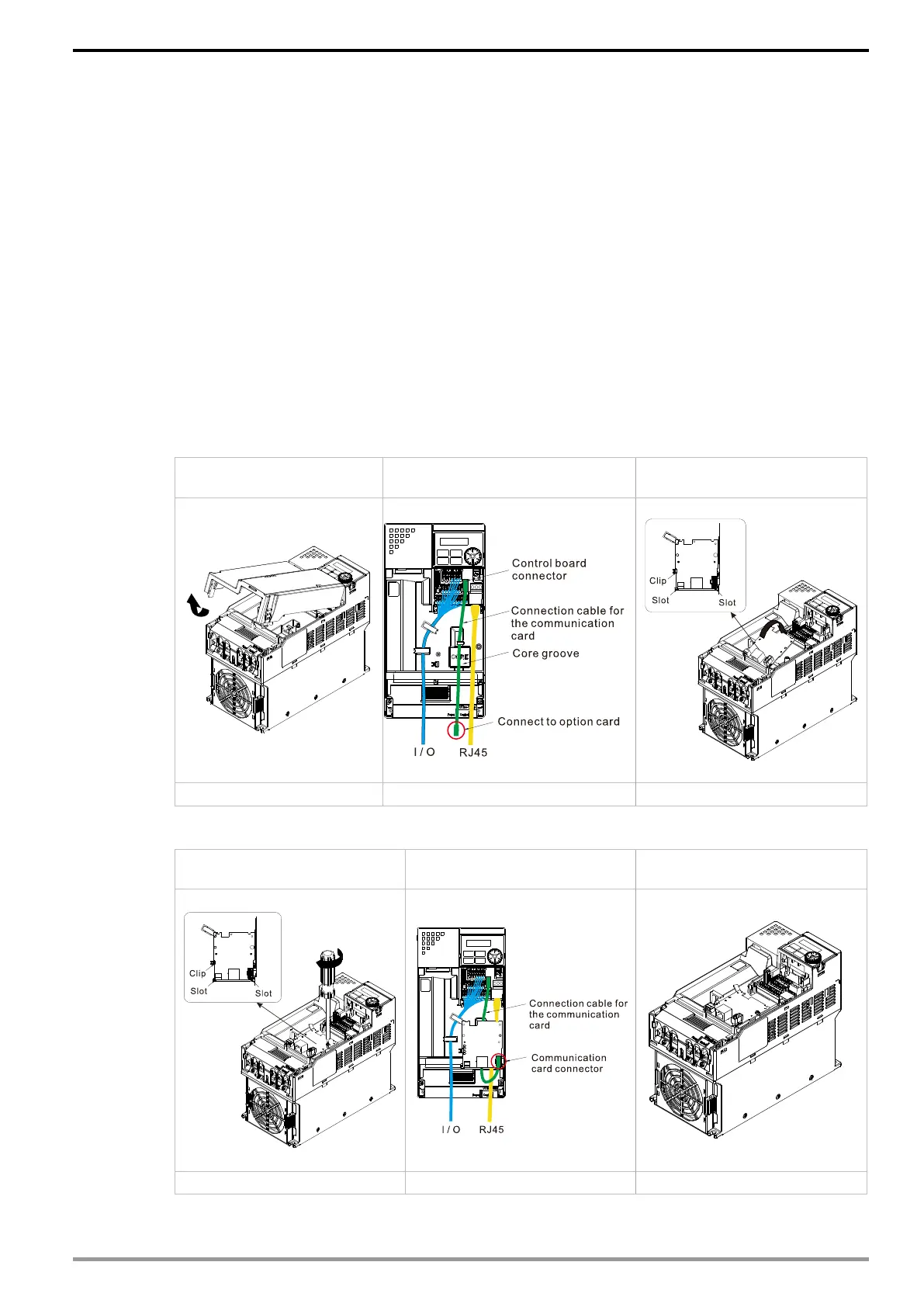
Turn off the power of the motor drive, and then remove the front cover, as shown in Fig.3-28.
Assemble the connection cable: Connect the connector at one end of the connection cable
to the control board connector. Refer to Section 3.2 for more information on connection
methods. Wire the cables as Fig.3-29 shows and make sure the core is placed in the
groove.
Assemble the communication card: Have the terminal block and connector of the
communication card face upward. Fix the front end of the communication card to the slots,
and then rotate it, as shown in the Fig.3-30.
Make sure that the clip properly engages the communication card, and then tighten the
screws (suggested torque value: 4–6 kg-cm [3.5–5.2 lb-in.] [0.39–0.59 Nm]), as shown in
Fig.3-31.
Assemble the connection cable: Connect the connector at the other end of the connection
cable to the connector of the communication card, as shown in Fig.3-32.
Assembly is completed, as shown in Fig.3-33.
Step1: Remove the
front cover
Step 2: Assemble the
connection cable
Step 3: Assemble the
communication card
Step 4: Tighten the
screws
Step 5: Assemble the
connection cable
Step 6: Assembly
completed