MS300/MH300 PROFINET Communication Card CMM-PN02
CMM-PN02 Operation Manual
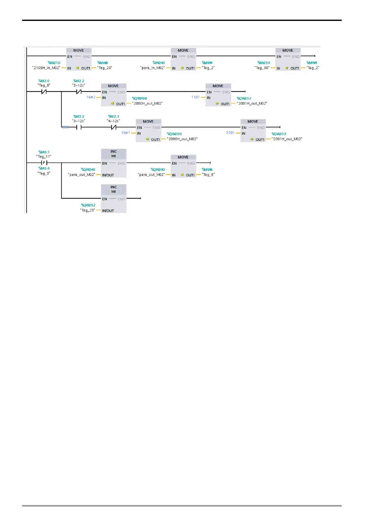
If you use a ladder diagram, you can implement the program below.
The first row maps 2105H of the motor drive through %IW210, %IW240, %IW254. It defines read
parameter 1 and read parameter 8 and puts them into internal variable %MW.
The second to third rows are for the motor drive control writing. Take address 2000 as an
example, when the second row indicates 0~3 seconds, use %QW200 to map 2000H to start the
motor drive. Then use %QW202 to map 2001H of the motor drive to set the frequency command
to 11.01Hz. When the third row indicates 3~12 seconds, stop the motor drive and set the
frequency command to 32.01Hz.
The fourth row and the fifth row are for the motor drive periodic parameter writing. Increase
%QW240 and %QW252 regularly so that the motor drive's user-defined writing parameter 1 and
user-defined writing parameter 7 can be increased.
NOTE: For the address setting of the user-defined parameters, refer to the description of
parameter reading and writing in the following sections.