MS300/MH300 PROFINET Communication Card CMM-PN02
CMM-PN02 Operation Manual
3.4 MH300 Installation
3.4.1 MH300 Mounting Position 1 (See Section 3.1 for Details on Mounting Position) -
Frame A–F
Installation method: Back-mount the communication card by connecting flat cables to
the control board.
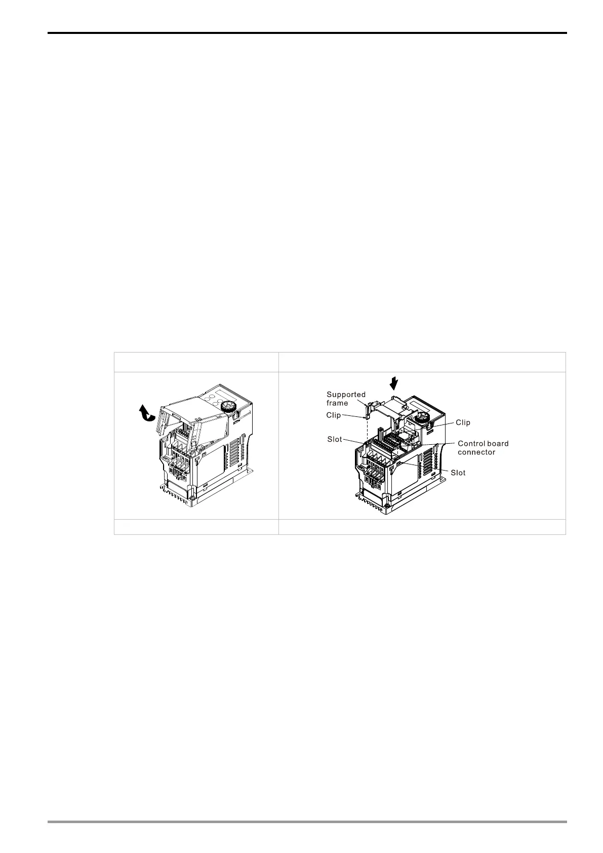
Turn off the power of the motor drive, and then remove the front cover, as shown in Fig.3-17.
Assemble the connection cable: Connect the connector at one end of the connection cable
to the control board connector. Refer to Section 3.2 for more information on connection
methods.
Assemble the supported frame of the option card: Aim the two clips at the two slots on the
motor drive, and then press downward to have the two clips engage the slots, as shown in
Fig.3-18.
Assemble the connection cable: Connect the connector at the other end of the connection
cable to the connector of the communication card.
Assemble the communication card: Have the terminal block and connector of the
communication card face downward, aim the two holes of the communication card to the
position column and press downward so that the three clips engage the communication card,
as shown in Fig.3-19.
Make sure that three clips properly engage the communication card, and then tighten the
screws (suggested torque value: 4–6 kg-cm [3.5–5.2 lb-in.] [0.39–0.59 Nm]), as shown in
Fig.3-20.
Assembly is completed, as shown in Fig.3-21.
Step1: Remove the front cover Step 2: Assemble the supported frame
Fig. 3-18