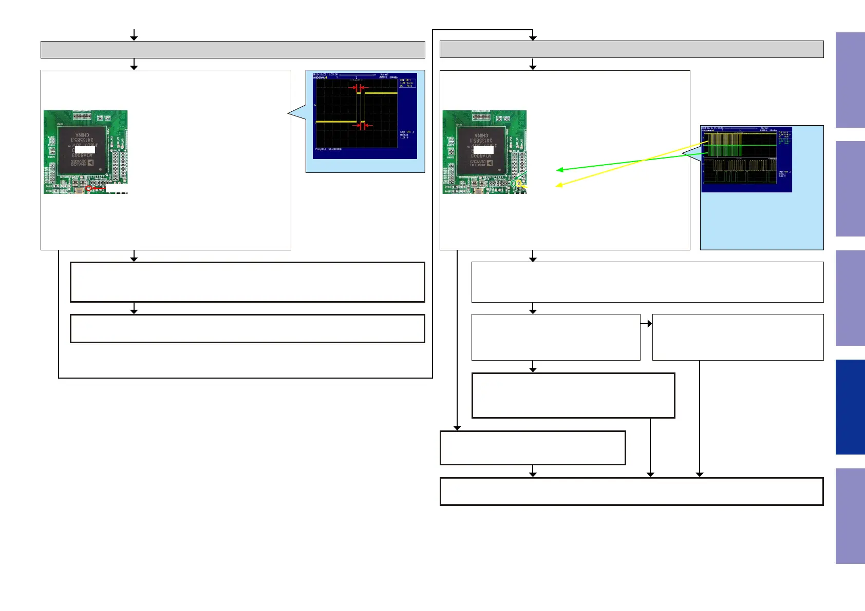
Check item(74). Checking the reset :
Check the CPU.
Is the waveform of the TP"TP113"near the GUI(IC401) correct (like
the one shown in the diagram) when the power is turned on?
IC401
TP113
Check item(75). Check the I2C communication line :
Check the CPU.
Is the waveform of the TP"TP110/111"near the GUI(IC401) correct
(like the one shown in the diagram) when the power is turned on?
IC401
TP111
TP110
Check item(76). Check the I2C communication line :
Check GUI (IC401), HDMI Decoder (IC351) and CPU(IC151) patterns as well as soldering.
If there is no problem, go to the next step.
Check the HDMI Decoder.
Remove the damping resistor (R3532/R353)
of HDMI Decoder (IC351).
Is the "I2C" waveform correct?
The GUI (IC401) is failure.
Replace with a new device.
Checking the reset waveform.
Check the I2C communication line.
10ms
10ms 10ms
Example of the waveform to be checked
The GUI (IC401) is failure.
Replace with a new device.
HDMI Decoder (IC351) is faulty.
Replace with a new device.
YES
Recheck from check item (1).
If it does not work, replace the PCB.
Check the reset circuit between CPU (IC151) and GUI (IC401).
If there is no problem, the GUI (IC401) is faulty.
Replace with a new device.
NOYES
*The diagram shows an example.
(Signal patterns vary depending on
the timing.)
Points for checking waveforms
- Crest value (3.3 V normally)
- Signal change
- SCL frequency (400 kHz normally )
NO
YES
YES
NO
Recheck from check item (1).
If it does not work, replace the PCB.
123
Caution in
servicing
Electrical Mechanical Repair Information Updating

 Loading...