Proceeding : TOP COVER → REAR PANEL → DIGITAL PCB
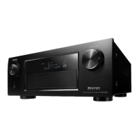
(1) Remove the screws. Remove the STYLE PIN. Cut the wire clamp, then remove the connector.
Remove the FFC.
(3) Remove the connector.
4. DIGITAL PCB
x1
CN781
CN704
FFC
FFC
CN321
CN903
CUT x3
Rivet
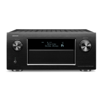
BN24A BN26A BN25A BN21A
BN23A
BN27A
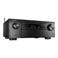
Proceeding : TOP COVER → REAR PANEL → DIGITAL PCB → VIDEO PCB
(1) Remove the connector. Remove the PCB HOLDER.
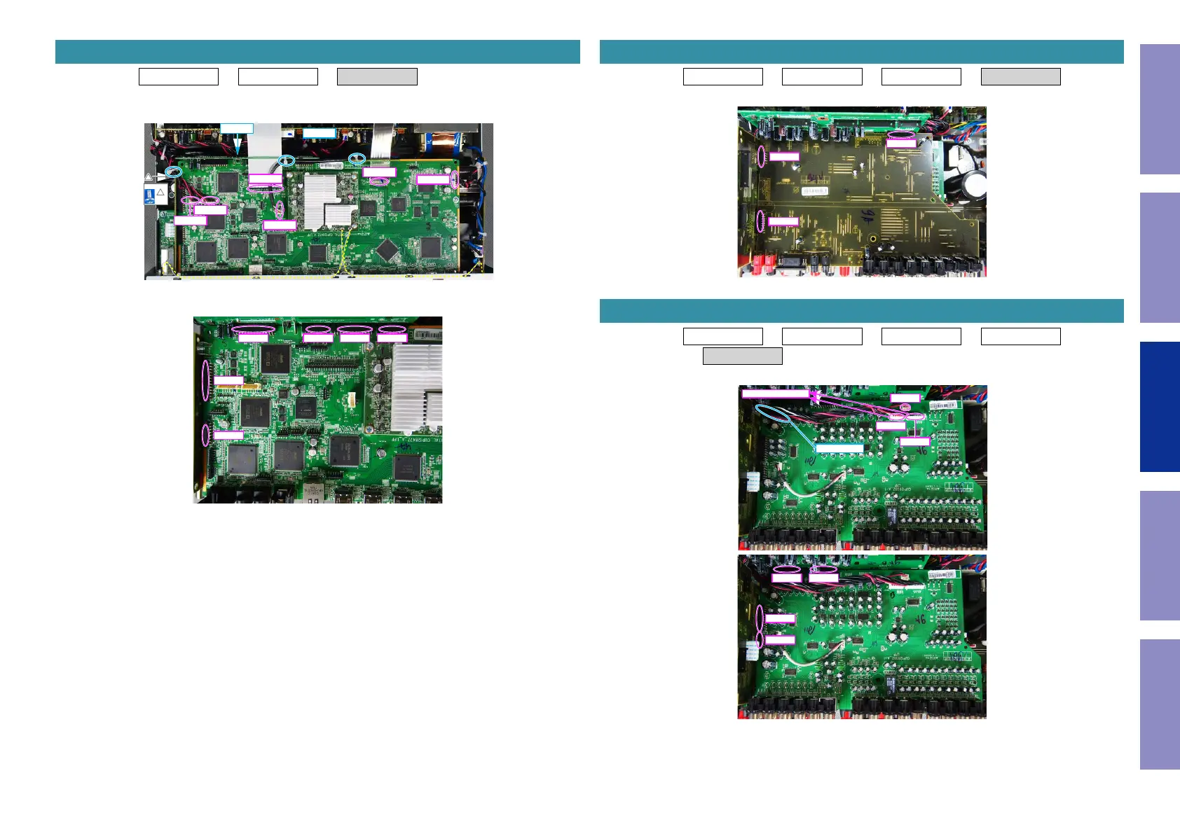
Proceeding : TOP COVER → REAR PANEL → DIGITAL PCB → VIDEO PCB
→ INPUT PCB
(1) Remove the screws. Remove the connector.
5. VIDEO PCB
BN21B
BN28B
BN27B
6. INPUT PCB
BN461
BN462
CN706
From AMP PCB
STYLE PIN
BN24C BN26C
BN23C
BN64C
75
Caution in
servicing
Electrical Mechanical Repair Information Updating

 Loading...