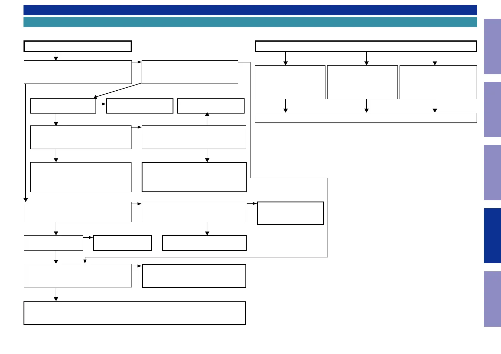
TROUBLE SHOOTING
1. POWER
0.6V or -0.6V
1.1. The unit does not power on
YES YES
NO
YES
NO
YES
NO
NO
Does the power indicator on the front panel
ash in green or white when the power is turned
on?
Is a fuse blown?
Does the power display on the front panel lights
green after approximately 10 seconds?
Check the voltage of [CN704 1 - 3 pin / CN781 1
pin] on the DIGITAL PCB while the power display
is ashing in green or white.
Remove the connector of the MAIN circuit board (CN971).
Check the "3-2. Protection History Display Mode"
The unit does not power on
Is a fuse blown?
Does the power shut down after several
seconds?
Is DC 5V being supplied from the SMPS PCB
(BN901) to the DIGITAL PCB?
See "1.2. Fuse is blown"
See "1.2. Fuse is blown"
Check the circuits around the Microprocessor
on the DIGITAL PCB and replace any faulty
parts.
TO "3-2. Protection History
Display Mode"
Are there any parts not fully connected into
the connectors that connect the PCBs?
Is DC5V output even when the connector
(CN903) supplying power from the SMPS PCB
to the DIGITAL PCB is removed?
Check the circuits around the Microprocessor
on the DIGITAL PCB and replace any faulty
parts.
Check for breakages and short circuits in the
circuits and parts between CN903 on the DIGI-
TAL PCB and the microprocessor power supply
and replace any faulty parts.
Connect the connectors correctly.
TO "6. SMPS"
YES
Check for leaks and short
circuits in the parts on the pri-
mary side. Replace any faulty
parts.
Blown fuse
Check the rectier diode in the
rectier circuit on the second-
ary side, and check for short
circuits. Replace any faulty
parts.
Replace the fuse after repair.
Check for short circuits between
the regulator output terminal and
GND in the power supply stabiliza-
tion circuit. Replace faulty parts if
there is a short circuit.
1.2. Fuse is blown
NO
NO
NO
YES
YES
0V
NO
YES
80
Caution in
servicing
Electrical Mechanical Repair Information Updating

 Loading...