5) Set each recording flag for Volts, Amps, kW, kVA, PF, and kVAR as desired.
6) Click Send Setup Table to Logger to send the setup table to the logger and make it the active table.
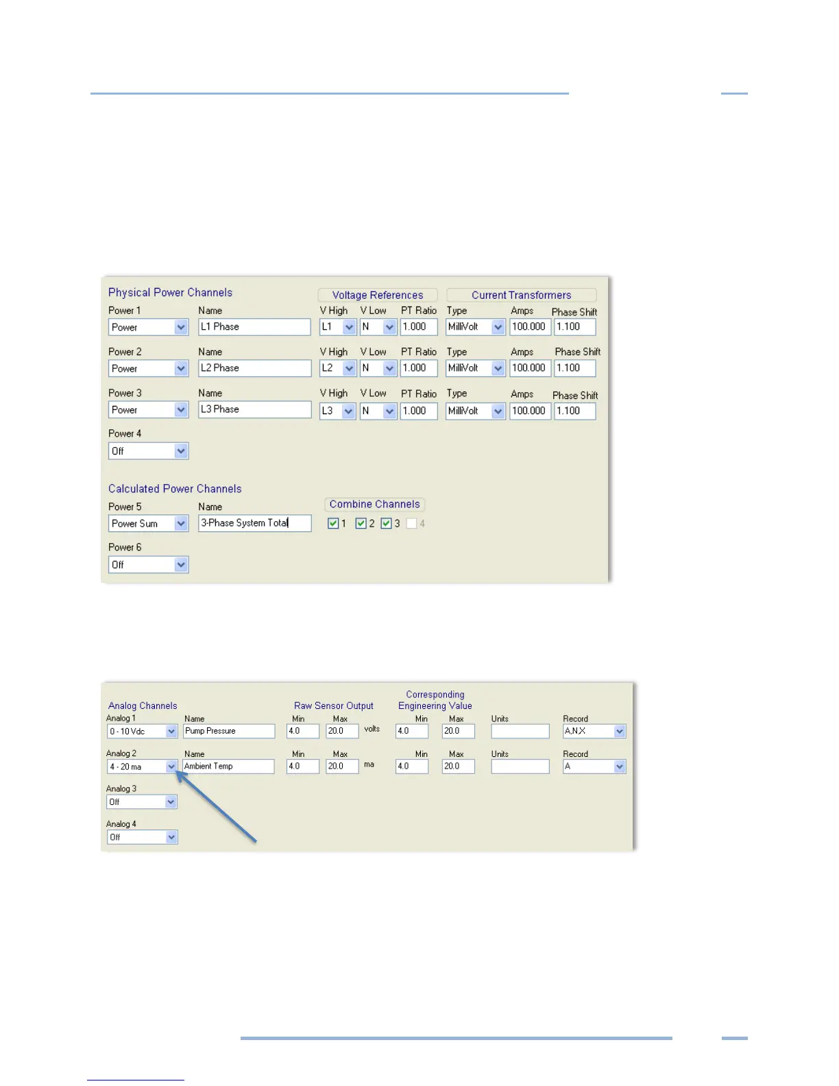
The following graphic is an example of a Setup Table for a 3-phase 4-wire connected load using a
Calculated Power Channel with Combine Channels 1, 2, and 3 selected to optimize memory usage on
the ELITEpro XC.
NOTE: The Recorded values listed to the right of the Current Transformers section on the Setup Table
are not shown in this graphic.
ANALOG OUTPUT CHANNELS
NOTE: Turn the analog channels on/off by choosing an option from the drop-down list.
1) Select Current/Voltage/Off from the drop-down menu for the channel type. Additional fields display
on the Setup Table screen when an analog channel current or voltage is selected.
2) Enter a descriptive name in the Name field to identify your measurement. This name appears in the
retrieved logger data header.