6159924330 - 08/2020 - 41 -
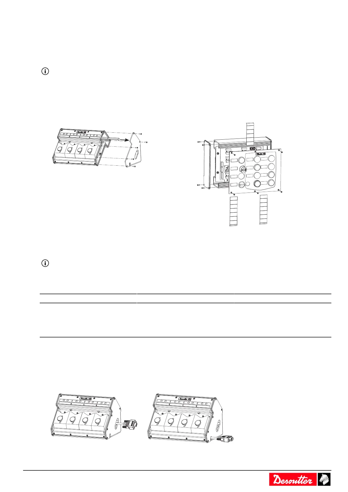
Remove the front and the right side panels by unscrewing the screws.
Wire and connect all connectors.
Pass the cables through the corresponding grommets.
Insert grommets Ø 0 when free space in order to ensure tightness.
Fit the cable entry sytem to the I/O expander by using the 4 screws M5x15 supplied in the kit.
The label marked 1 corresponds to the upper row of connectors.
Labeling
Disassembly
Loosen the screws as shown in the examples below.
Remove the labels and write the description with a pencil.
Reassembly
Ensure that the seal is correctly mounted.
Add some glue (Loctite 243) to the screws and tighten to 1.5 Nm to the right.
eBUS cables
Length (m) Length (ft) Part number
1 3.3 6159176070
3 9.9 6159176080
5 16.4 6159176090
15 49.2 6159176100
eBUS termination plug: 6159176250
Connecting eBUS cable to the accessories
eBUS cable routing
Before connecting socket trays and bit trays, select how to pass the cable as shown below.

 Loading...