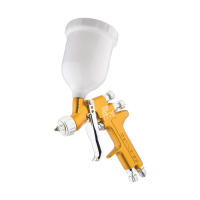
TB-1022
6
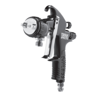
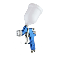
INSTALLATION
For maximum transfer efciency, do not use more pressure than
is necessary to atomise the material being applied.
1. Connect the gun to a clean, moisture and oil free air
supply using a hose size of at least 8 mm (5/16") I.D. hose.
Do not use 6 mm I.D. hose (8 m x 6 mm hose at 510 LPM
has a pressure loss of 1.8 bar. 8 m x 8 mm hose at 510 LPM
has a pressure loss of 0.6 bar. [Do not use 1/4" I.D. hose
(25' x 1/4" hose at 18 CFM has a pressure loss of 25 psi.
25' x 5/16" hose at 18 CFM has a pressure loss of 8 psi).]
Depending on hose length, larger I.D. hose may be required.
NOTE
When gun is triggered on, adjust inlet air pressure
(for recommended pressures see Chart 1 under Parts
Replacement) at the gun inlet. (Pressure gauge shown under
Accessories is recommended for this). Do not use more
pressure than is necessary to atomise the material being
applied. Excess pressure will create additional overspray and
reduce transfer efciency.
NOTE
If quick connects are required, use only high ow quick
connects approved for HVLP use. Other types will not ow
enough air for proper gun operation.
NOTE
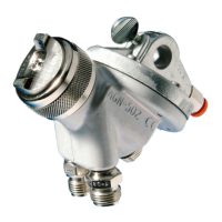
If an air adjusting valve is used at the gun inlet, use a DeVilbiss
air adjusting valve. Some competitive adjusting valves have
signicant pressure drop that can adversely affect spray
performance. DeVilbiss air adjusting valves have minimal
pressure drop.
2. Attach the uid supply hose to the uid inlet connector.
NOTE
Protective coating and rust inhibitors have been used
to keep the gun in good condition prior to shipment.
Before using the gun, ush it with solvents so that these
materials will be removed from uid passages.
OPERATION
1. Mix coating material to manufacturer’s instructions and strain
material.
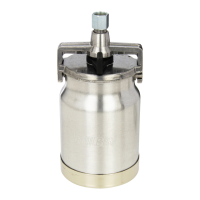
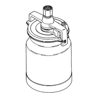
2. Fill the pressure cup with the required amount of material.
DO NOT OVERFILL.
3. Attach Cup Lid.
4. Turn uid adjusting knob (28) clockwise to prevent uid
needle movement.
5. Turn spreader valve adjusting knob (16) counter clockwise to
fully open.
6. Trigger gun on and adjust inlet air pressure (for
recommended gures see Chart 1 under Parts Replacement)
at the gun inlet. (Pressure gauge shown under Accessories is
recommended for this).
7. Turn uid adjusting knob (28) counter clockwise until rst
thread shows and turn on the supply air to the pressure cup.
8. Test spray. If the nish is too dry, reduce airow by reducing
air inlet pressure.
9. If nish is too wet, reduce uid ow by turning uid adjusting
knob (28) clockwise. If atomisation is too coarse, increase inlet
air pressure. If too ne, reduce inlet pressure.
10. The pattern size can be reduced by turning spreader valve
adjusting knob (16) clockwise.
11. Hold gun perpendicular to surface being sprayed. Arcing
or tilting may result in uneven coating.
12. The recommended spray distance is 150-200 mm (6"–8").
13. Spray edges rst. Overlap each stroke a minimum of 75%. Move
gun at a constant speed.
14. Always turn off air supply and relieve pressure when gun is not
in use.
PREVENTIVE MAINTENANCE & CLEANING
To clean air cap and uid nozzle, brush exterior with a stiff bristle
brush. If necessary to clean cap holes, use a broom straw or
toothpick if possible. If a wire or hard instrument is used, extreme
care must be used to prevent scratching or burring of the holes which
will cause a distorted spray pattern.
To clean uid passages, remove uid supply hose, then ush with a
suitable solvent. Wipe gun exterior with a solvent dampened cloth.
Never completely immerse in solvent as this is detrimental to the
lubricants and packings.
NOTE
When replacing the uid nozzle or uid needle, replace both
at the same time. Using worn parts can cause uid leakage.
See page 11, Chart 2. Also, replace the needle packing at this
time. Lightly lubricate the threads of the uid nozzle before
reassembling. Torque to 18–20 Nm (13–15 ft-lbs). Do not over
tighten the uid nozzle.
CAUTION
To prevent damage to uid nozzle (8) or uid needle (24), be
sure to either 1) pull the trigger and hold while tightening or
loosening the uid nozzle, or 2) remove uid adjusting knob (28)
to relieve spring pressure against needle collar.
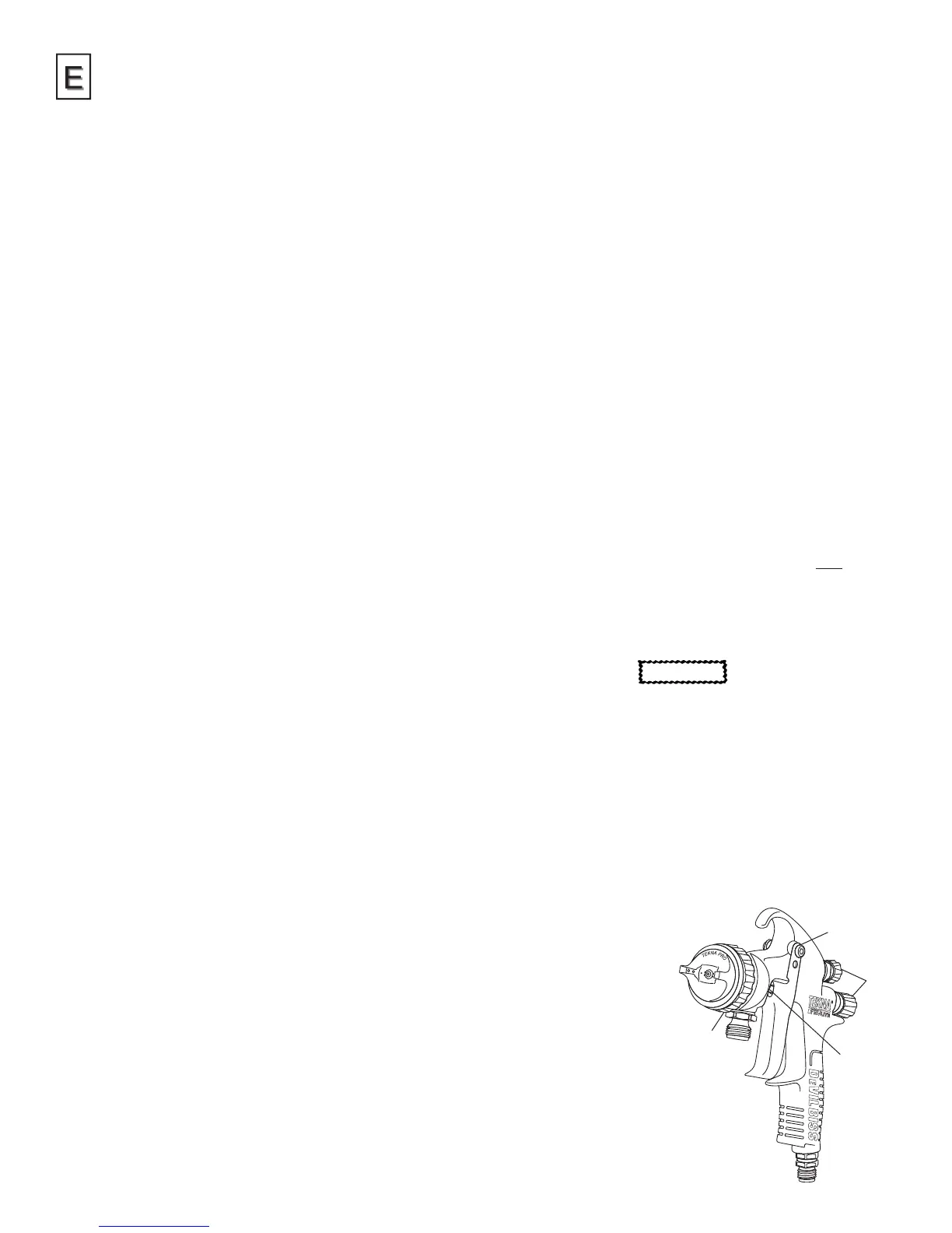
SPRAY GUN LUBRICATION
Daily, apply a drop of spray gun lubricant at trigger stud (40). The
shank of uid needle (24) where it enters packing nut (36) should
also be oiled. Fluid needle packing (34) should be lubricated
periodically. Make sure spray head (9) and air cap retaining ring (1)
threads are clean and free of foreign matter. Before assembling air
cap retaining ring to spray head, clean the threads thoroughly, then
add two drops of spray gun lubricant to threads. Fluid needle spring
(25) and air valve spring (21) should
be coated with a very light grease,
making sure that any excess grease
will not clog the air passages.
Points of Lubrication
A. Trigger Points
B. Packing
C. Adjusting Knobs
D. Air Cap Retaining Ring Threads
A
C
D
B