TB-1022
11
Parts Replacement/Maintenance
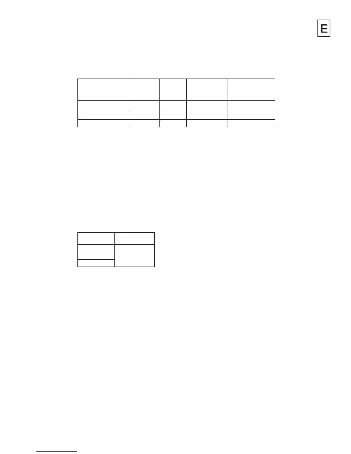
Chart 1 – Air Caps
ORDER NO. FOR
AIR CAP
TECHNOLOGY MARKING
ON AIR CAP
NOMINAL
OPERATING GUN
INLET PRESSURE
BAR/PSI
AIR FLOW
LPM/SCFM
PRO-103-HV40 HVLP HV40 (1.2) / 17
(for compliance)
(298) / 10.5
PRO-103-TE20 High Efciency TE20 (1.8 – 3.5) / 26 – 50 (340 – 550) / 12 – 19.4
PRO-103-TE40 High Efciency TE40 (2.0 – 3.5) / 29 – 50 (368 – 550) / 13 – 19.4
NOTE 1: Guns with HVLP caps must not exceed 0.7 bar (10 psi) air cap pressure with
gun fully triggered. (Aproximately 17 psi gun inlet pressure.) (See accessories
for air cap test kit which is available to set the exact cap pressure.)
When used with high efciency caps and Automotive Renishing materials,
these spray guns have been found to exceed 65% transfer efciency under
recommended conditions.
NOTE 2: When removing air cap from retaining ring, don’t remove slip ring (2)
or retaining ring seal (5) from retaining ring. Damage to the parts may
occur. Slip ring and retaining ring seal are not available as replacements.
Simply wipe parts clean and reassemble with new or clean air cap.
Chart 2 – Fluid Nozzles & Fluid Needles
PART NO. ON
FLUID NOZZLE
PART NO. ON
FLUID NEEDLE
PRO-205-10-K PRO-320-085-10K
PRO-205-12-K
PRO-320-12-14-K
PRO-205-14-K
NOTE: When replacing the uid nozzle or uid needle, replace both at the same time.
Lightly lubricate the threads of the uid nozzle before reassembling. Torque
to 18–20 Nm (13–15 ft-lbs). Don’t over tighten the uid nozzle. Use 10 mm
wrench supplied with gun.