TC500 Ethernet Cabling Certifier Operation Manual
16
7.1. Connect instrument to the cable
According to TIA/EIA-568-B or ISO/IEC 11801, there are two transmission paths to be certified: channel and permanent link. When
certify permanent link cabling, connect main unit to the near end outlet A using one equipment cord and connect remote unit to
the far end outlet B using the other equipment cord (Figure 18). When certify channel cabling, connect main unit to the near end
work area cord C1 and connect remote unit to the far end work area cord C2 (Figure 18).
NOTE: In order to extend the service life of RJ45 connector, please connect the RJ45 M-F connector to the RJ45 connector.
7.2. Auto Test
The Auto Test runs some or all of the tests listed below, depending on the selected test limit.
Wire map
Length
Propagation delay
Delay skew
d. c. loop resistance
Insertion loss (attenuation)
NEXT (near-end crosstalk)
PS NEXT (power-sum NEXT)
Return loss
ACR (attenuation to crosstalk ratio at the near end)
PS ACR ( power-sum ACR-N)
ELFEXT ( equal level far-end crosstalk)
PS ELFEXT (power-sum ELFEXT)
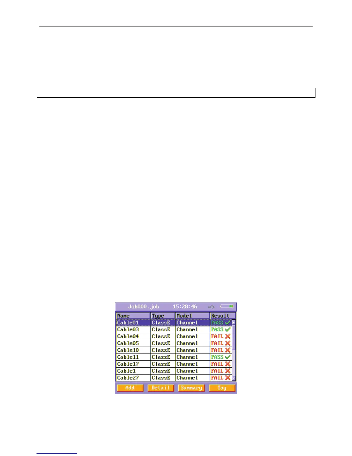
In the main menu, press “Auto Test ” function button to enter Auto Test menu.
Figure19 Auto Test menu
In Auto Test menu, there is a list of cables in the current job folder. To test a new cable, press Add soft function key. Then a new
cable appears.