57
Masking Ring (door lock cover) Removal
A. Remove front panel.
B. Remove nuts that retain masking ring.
C. Move it to the left and off.
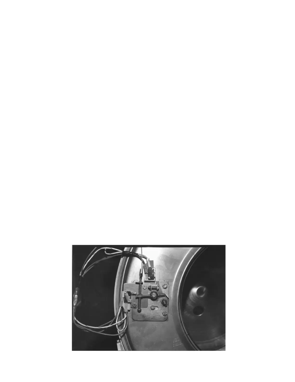
Door Lock Assembly
After removing the front panel and trim ring, the door lock assembly can now be accessed.
Operation
After loading the clothing, the door should be closed and latched. The locking cam on the door contacts the
latching switch actuator which closes the latching switch. The specified number of coins should now be added
to start the washer. This satisfies the coin accumulator which powers the timer rapid advance motor. A timer
contact provides power to the latching switch and with the door latched, the power travels through the latching
switch to the door lock solenoid. This solenoid pulls up on the locking pawl by use of a linkage rod. The
locking pawl has two jobs. The first is to lock the door. This is accomplished by blocking the locking cam on
the door so that it can't rotate to unlock. The second job is to close the two piggyback lock sensing switches.
These switches control power to all of the controls. If the door unlocks for any reason, these two switches will
stop the machine. When the door handle is 1/4 to 1/2 of an inch from its fully closed position, the latching
switch should close. The two piggyback lock sensing switches should be open when the door is unlocked and
should be closed when the door is locked.
Adjustment
The latching switch and the piggyback lock sensing switches all have slotted mounting for easy adjustment.
1. Set door cam over pin.
2. Tighten spring screw on switch actuator arm until it just clears cam OD. ( Note : Spring screw will
have approx. 1/8" thread exposed at end beyond nut.)
3. Set .040 thickness gage between arm and latch switch operator.
4. Swivel switch until it clicks closed. Back it up just until it clicks for a reset. Tighten in that position.
Check again for close and rest with gage in place. Remove gage.
5. Check for switch actuation at partial turn of cam as in operation above.
6. Check that lock arm swings by cam lobe to lock position when switch just clicks.
The next two pages have photos and text to aid in adjustment procedures.
 Loading...