Maintenance Manual LS8
Issued: December 2009
Copyright DG Flugzeugbau GmbH - any copy or publishing prohibited
Manual valid with the up-to-date cover page only
4-1
4 Working instructions
4.1 Removal and installation of control surfaces
4.1.1 Ailerons
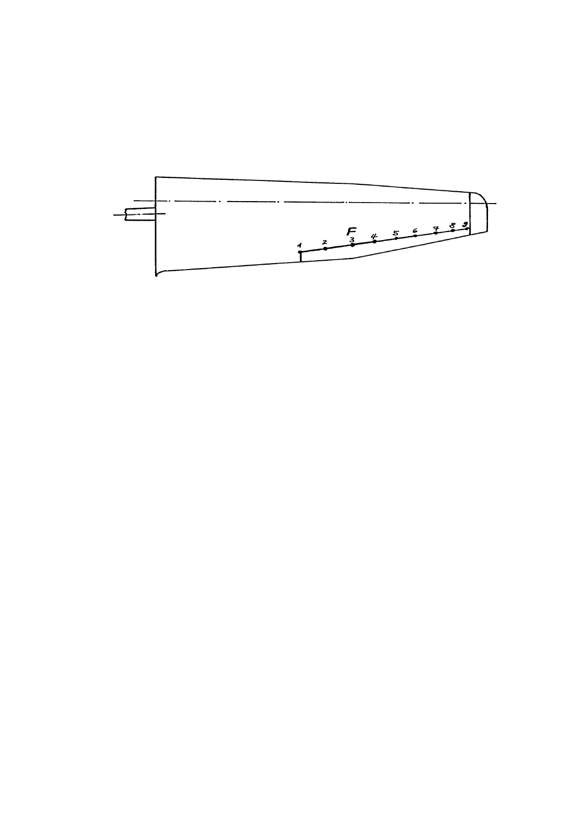
Wing scheme with aileron bearings (15 m version shown)
F = laterally fixed bearing
Removal of ailerons
(1)
Remove winglet or wing Tipp extension.
(2)
LS8:
remove lower side gap seal (convex plastic or metal strip) and inner
seals tape (Teflon tape) completely.
LS8-a, LS8-b, LS8-18:
remove inner seals tapes (Teflon tape)
completely, upper and lower side.
(3)
Lift bonded-on drive covers cautiously using knife.
(4)
Disconnect drive rods from aileron (6 mm thread, nut M6 LN9348 or
DIN985-8 zn, width over flats 10mm), remember sequence and
position of washers, if applicable.
(5)
Loosen nut (6 mm thread, M6 LN9348 or DIN985-8 zn, width over
flats 10 mm) from bearing No. 3 (fixed bearing), remember sequence
and position of washers.
(6)
deflect ailerons fully downwards, then remove outer aileron, then inner
aileron (
only LS8
) from bearing pins towards wingtip. Use two persons
to avoid damage, low bending stiffness.
(7)
Watch washers, if existent, at inner side of bearing pin of fixed bearing
No. 3.
(8)
Only
LS8-b, LS8-18:
18 m wingtip aileron may be removed from tip
towards fuselage after removing both inner seals tapes completely
(Teflon tape). Inner tip “bearing” intentionally has no bushing pressed
in !