Hardware Development boards
Digi XBee® 3 Cellular LTE Cat 1 AT&T Smart Modem User Guide
114
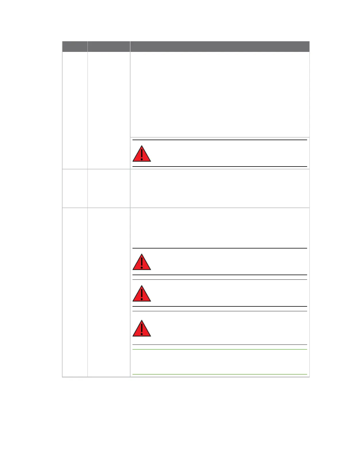
Number Item Description
1 Secondary USB
(USB MICRO B)
and DIP Switch
Secondary USB Connector for direct programming of modules on some
XBee units. Flip the Dip switches to the right for I2C access to the
board; flip Dip switches to the left to disable I2C access to the board.
The USB_P and USB_N lines are always connected to the XBee,
regardless of Dip switch setting. USB communications will fail if
switches are not in the left position or if XBEE is not configured to
enable USB communications. See ATP1 command.
This USB port is not designed to power the module or the board. A USB-
C cable or battery port is required to power the board. Cable can be
connected at any time, with the XBe powered or unpowered.
WARNING! USB micro port should not be connected when
used with XBees that do not support USB communications.
2 Current
Measure
Large switch controls whether current measure mode is active or
inactive. When inactive, current can freely flow to the VCC pin of the
XBee. When active, the VCC pin of the XBee is disconnected from the 3.3
V line on the development board. This allows current measurement to
be conducted by attaching a current meter across the jumper P10.
3 Battery
Connector
If desired, a battery can be attached to provide power to the
development board. The voltage can range from 2 V to 5 V. The positive
terminal is on the left.
If the USB-C connector is connected to a computer, the power will be
provided through the USB-C connector and not the battery connector.
WARNING! Battery current discharge rating must be enough
to support 5 W or more.
WARNING! There is no circuit to prevent over discharge of
battery. Battery must contain its own protection circuitry.
WARNING! Move UART switches to the left (OFF position)
when using battery or external power or for the XBee and
the USB-C connector is not powering the UART.
Note Power supply outputs 3.3V to XBee regardless of input voltage as
long as current requirement can be met to achieve power consumption
of devices.