Hardware Development boards
Digi XBee® 3 Cellular LTE Cat 1 AT&T Smart Modem User Guide
115
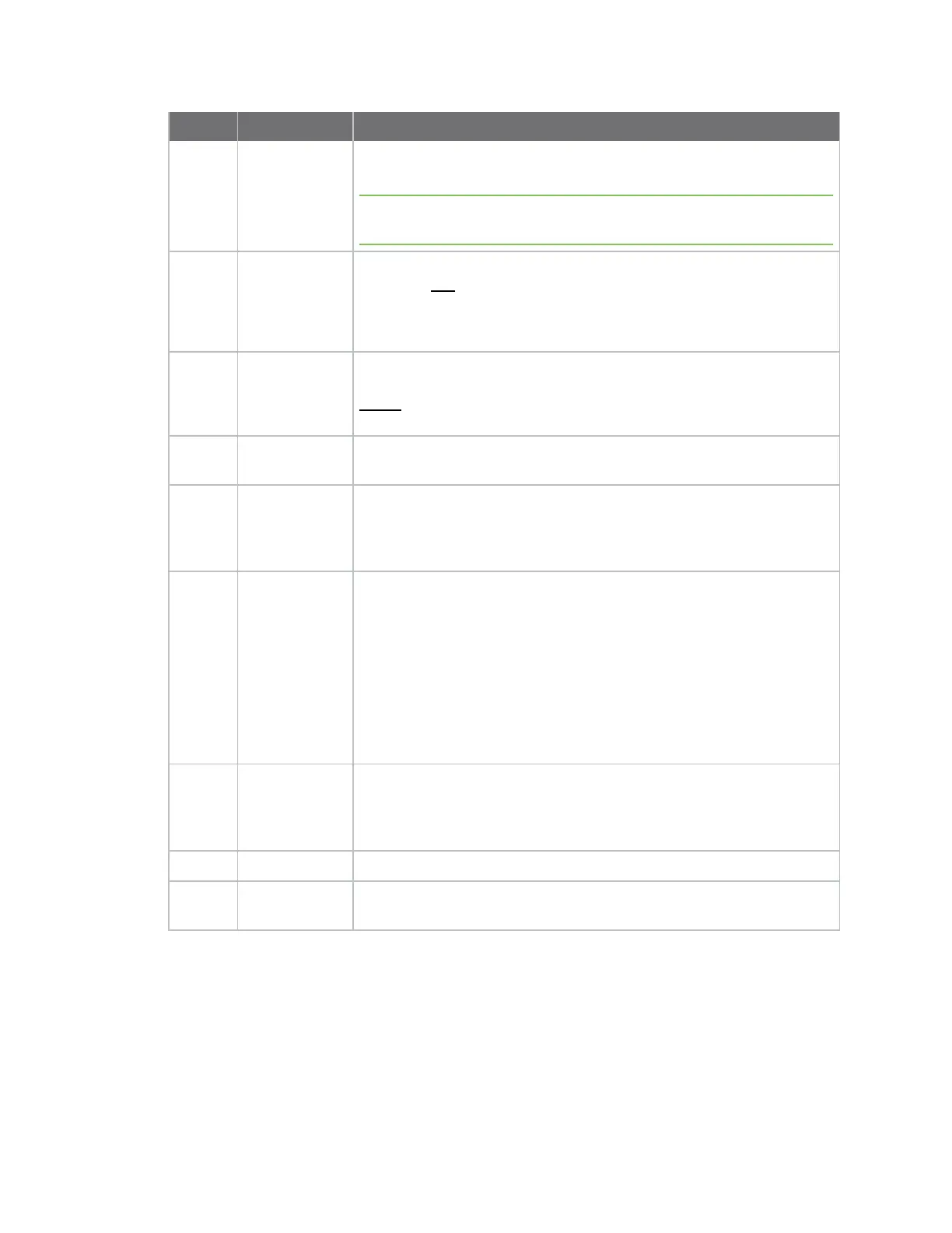
Number Item Description
4 USB-C
Connector
Provides power and UART communications for the XBEE and
development board.
Note Requires USB 3.0 to supply 1 amp of required current. USB 2.0
ports that cannot supply at least 1 amp cannot be used.
5 LED indicator Red: UART DOUT (modem sending serial/UART data to host)
Green: UART DIN (modem receiving serial/UART data from host)
White: ON/SLP/DIO9
Blue: Connection Status/DIO5
Yellow: RSSI/PWM0/DIO10
6 User Buttons Comm DIO0 Button connects the Commissioning/DIO0 pin to GND when
pressed.
RESET button resets the XBee module when pressed.
7 Breakout
Connector
This 40 pin connects to various XBee pins as shown on the silkscreen on
the bottom of the board.
8 UART Dip
Switch
Push Dip switches to the right (OFF position) to disconnect USB-to-
UART conversion chip from the XBee. This allows UART lines to be
individually selected to connect through the breakout connector or the
USB-C interface.
9 Grove
Connector
This connector attaches I2C-enabled devices to the development board.
Note that I2C needs to be available on the XBee in the board for this
functionality to be used.
Move both USB direct connect switches to the right (closed position)
and disconnect the USB micro port for correct operation of the I2C to
connector.
Pin 1: I2C_CLK/XBee DIO1
Pin2: I2C_SDA/XBee DIO11
Pin3: VCC
Pin4: GND
10 Temp/Humidity
Sensor
This part is a Texas Instruments HDC1080 temperature and humidity
sensor connected through I2C on XBee pins DIO1 and DIO11. Move both
USB direct connect switches to the right (closed position) and
disconnect the USB micro port for correct operation of the I2C sensor.
11 XBee Socket This is the socket for the XBee (TH form factor).
12 XBee Test
Point Pins
Allows easy access to pins 1 to 20 of the XBee.