003 Family Setup Guide70
Analog Inputs
Mic Inputs 1–8
These are balanced, three-conductor XLR con-
nectors for microphone-level analog inputs.
Gain is controlled by the corresponding Input
Gain Control knob (located on the front panel
of 003 Rack+). The source (Mic, Line, or DI) is
chosen using the front panel Line-DI switch.
An unlit Line/DI switch means the mic (XLR) in-
put is active.
Line/DI Inputs 1–8
The combination Line/DI (“Direct Input,” “Di-
rect Inject,” or “Direct Interface”) inputs accept
both balanced 1/4-inch balanced TRS connec-
tors (for outboard effects and other line-level
sources) and unbalanced 1/4-inch TS connectors
(for guitars and other instrument level sources).
Gain is controlled by the corresponding Input
Gain knob (located on the front panel of
003 Rack+). The source (Mic, Line, or DI) is cho-
sen using the Line-DI switch.
An enabled (lit) Line-DI switch means the
Line/DI (1/4-inch) input is active.
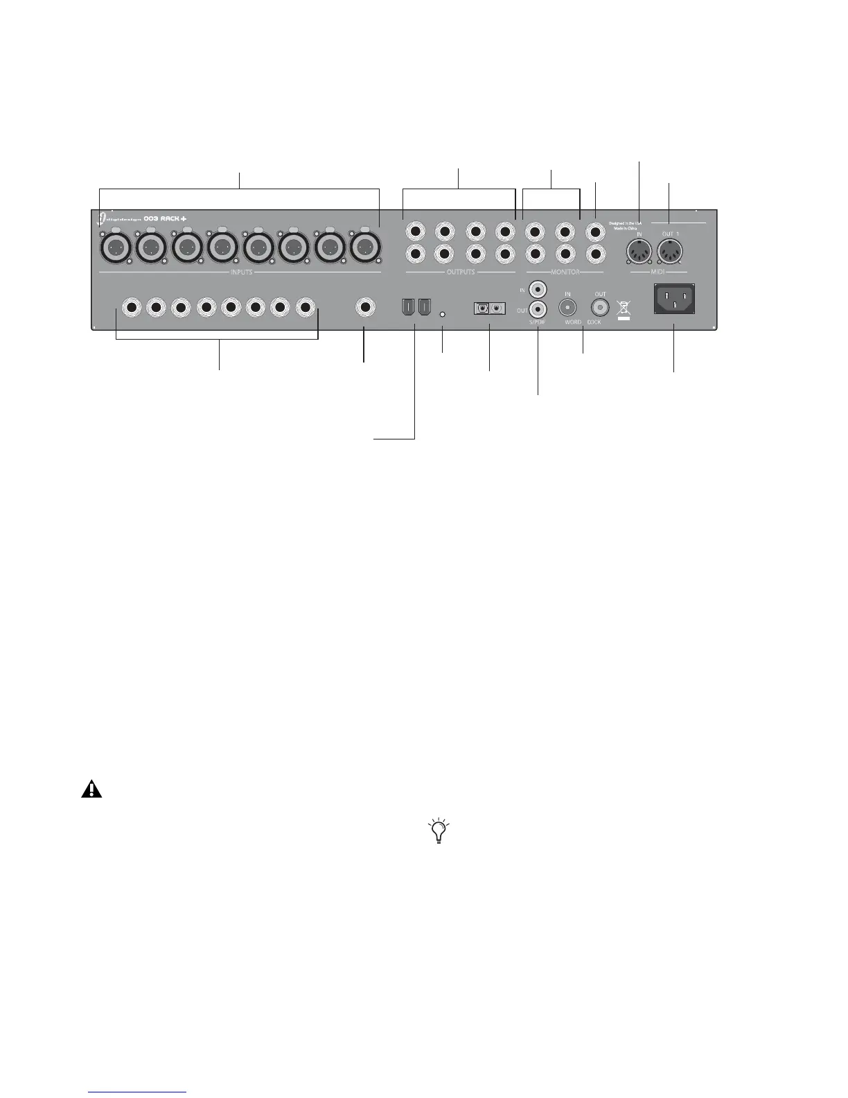
Figure 5. 003 Rack+ back panel
12
3
4
5
6
7
8
1
2
3
4
5
6
7
8
L
R
L
R
L
R
OUTPUTS
MAIN
MONITOR
MIDI
ALT AUX IN
FOOT SWITCH LINK1394
OUTIN
OPTICAL
AC ~ 100-240V;50-60HZ; 1A
S/N
INPUTS
Designed in the USA
Made in China
LINE / DI
1
2
3
4
5
678
Mic inputs 1-8
Line/DI inputs 1-8
Link indicator
Analog Outputs 1-8
Main and Alt
FireWire ports
Monitor Outputs
Aux In
MIDI In
MIDI Out
Footswitch
Optical I/O
S/PDIF I/O
Word Clock
AC power connector
The XLR connectors on Inputs 1–8 are
wired specifically to match the impedance
of microphones. Do not use these XLR con-
nectors for line inputs; use the 1/4-inch con-
nectors instead.
If you have an instrument connected to the
front panel DI 1 input and you have a line
or DI input connected to the rear panel
channel 1 Line/DI input, the front panel DI
1 input takes precedence over the rear panel
channel 1 Line/DI input.
 Loading...