DIGITAL-LOGIC AG MSM586SEN/SEV Manual V1.5E
80
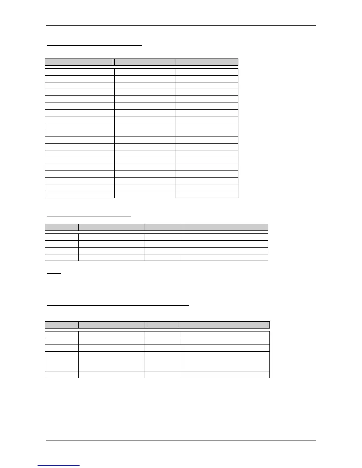
P1 Printerport (Centronics)
The printer connector provides an interface for 8 Bit centronics printers.
Header onboard: D-SUB connector: Signal
Pin 1 Pin 1 = Strobe
Pin 3 Pin 2 = Data 0
Pin 5 Pin 3 = Data 1
Pin 7 Pin 4 = Data 2
Pin 9 Pin 5 = Data 3
Pin 11 Pin 6 = Data 4
Pin 13 Pin 7 = Data 5
Pin 15 Pin 8 = Data 6
Pin 17 Pin 9 = Data 7
Pin 19 Pin 10 = Acknowledge
Pin 21 Pin 11 = Busy
Pin 23 Pin 12 = paper end
Pin 25 Pin 13 = select
Pin 2 Pin 14 = autofeed
Pin 4 Pin 15 = error
Pin 6 Pin 16 = init printer
Pin 8 Pin 17 = shift in (SI)
Pin 10,12,14,16,18 Pin 18 - 22 = left open
Pin 20,22,24 Pin 23 - 25 = GND
J48 Power supply / IrDA
Pin Signal Pin Signal
Pin 1 = GND Pin 2 = Vcc suspend (+5V)
Pin 3 = NC Pin 4 = +12Volt (for LCD backlight)
Pin 5 = Fast IrDA_TX (TTL) Pin 6 = Fast IrDA_RX (TTL)
Pin 7 = GND Pin 8 = Vcc suspend (+5V)
Rem:
Fast IrDA is directly connected to the SUPER I/O (TX=pin 82; RX= pin 81). Drivers have to be written by the
customer.
J27 Utility- connector, PS/2- mouse- keyboard
Attention: The speaker must be connected to VCC, to have a low inactive current in the speaker !
Pin Signal Pin Signal
Pin 1 = Speaker out Pin 2 = Ground
Pin 3 = Reset In Pin 4 = VCC
Pin 5 = Keyboard data Pin 6 = Keyboard clock
Pin 7 = Ground Pin 8 = External battery 3.0V
(since V2.2)
read also chapter 4.5.3
Pin 9 = PS/2 mouse clock Pin10 = PS/2 mouse data