DS5 Isolated Bipolar Constant Current Stimulator DS5 Operator's Manual 5.0
CHAPTER 2
CHAPTER 2
HARDWARE INSTALLATION
HARDWARE INSTALLATION
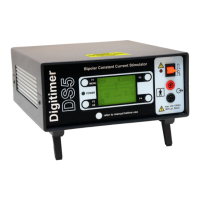
Tour of the Hardware
Introduction
The DS5 is an isolated bipolar constant current stimulator specifically designed for studies of the peripheral
nervous system in both diagnostic and research settings and is ideal for excitability studies based on
threshold tracking protocols. Unlike other percutaneous nerve stimulators such as our own DS7A, the DS5
does not produce a traditional “square” stimulus pulse but instead is able to receive a bipolar voltage
waveform from another device and convert this into a bipolar constant current stimulus of the same shape
and time course.
For optimum flexibility, the DS5 can accept four voltage input ranges (±1V, ±2.5V, ±5V, ±10V) from the
waveform source, which it uses to produce an isolated output current up to a maximum ±50mA for patient
stimulation. The input voltage signal is fed into the DS5 via a BNC socket on the rear of the stimulator. The
other pair of BNC sockets, which are used for stimulus monitoring, output a voltage waveform proportional
to the actual stimulus voltage or current supplied to the patient.
Appropriate stimulation electrodes should be connected via the pair of 4mm touch proof output sockets (red
and black) on the front of the unit or 1.5mm DIN 42 802-1 style connectors via the optional D185-HB4
Electrode Extension Cable.
Stimulus parameters and settings, including the input and output ranges are displayed on a backlit LCD
screen on the front of the unit. Modification of these parameters is made possible by use of the function
keys (F1 to F4) situated at each corner of the display screen.
The front panel of the DS5 also features an output enable/disable switch, as well as both power and warning
LEDs. The rear of the DS5 includes an equipotential connection point, mains IEC inlet (power) socket, fuses,
mains voltage selector and a mains on/off switch.
Front Panel Components
1. Function Keys - Numbered F1 to F4. These keys are arranged at the four corners of the LCD
display. Their functions are dynamically assigned depending upon the status of the DS5 LCD
display.
2. Green Power LED - Indicates when the DS5 rear panel switch is in the ON position.
3. Illuminated LCD Display - This is the primary operator interface, displaying all current operating
conditions as well as F key assignments, stimulation data and configuration menus.
4. Red & Black Isolated Output Sockets (4mm touch proof type) - The Red will go positive with
respect to the Black socket when positive voltages are applied to the Voltage Input BNC socket on
the rear of the DS5. The reverse will be true when negative voltages are applied at that socket.
5. Output Enable/Disable/Reset Toggle Switch - This momentary action toggle switch is used to
enable, disable or reset the DS5. Upward deflection enables the output and downward deflection
disables a previously enabled output. Downward deflection can also be used to reset the DS5 when
Digitimer Ltd. 19 of 52 Copyright © 2009