DS5 Isolated Bipolar Constant Current Stimulator DS5 Operator's Manual 5.0
Equipment complies with all current
European Union directives.
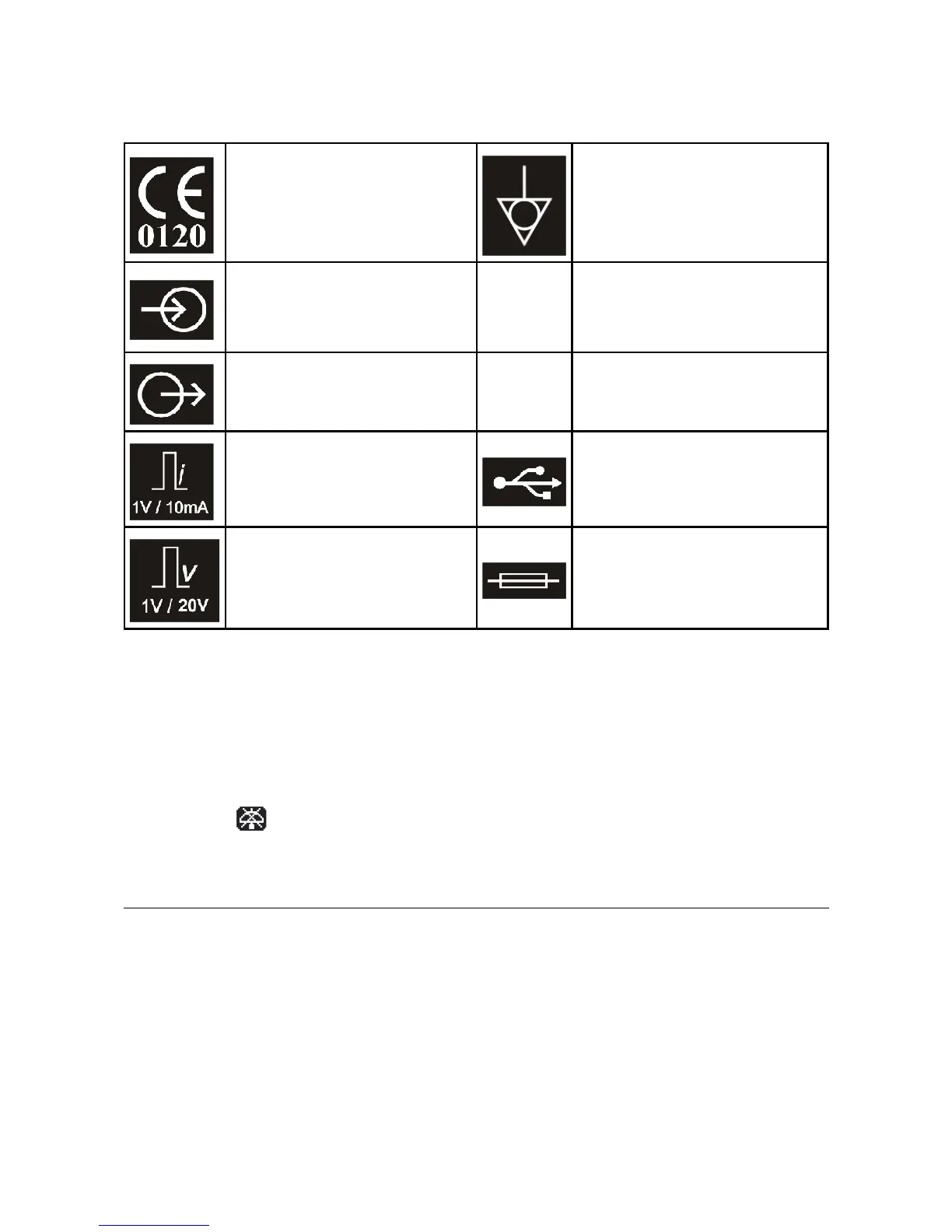
Potential Equalisation Connector
(PEC).
Signal Input (±10V max). The
voltage applied at this input
determines the shape of the
stimulus waveform.
o
OFF (power) - Indicates OFF position
of Mains Power switch.
Monitor Output – Voltage outputs
which are calibrated to the stimulus
current or voltage (see below)
I
ON (power) – Indicates ON position
of Mains Power switch.
Monitor Output (Current)
Scaling – 1V/10mA.
Control Input – USB socket for
connection to computer.
Monitor Output (Voltage)
Scaling – 1V/20V.
Mains inlet fuse – replace with type
indicated for your local mains
voltage, unless this has already been
factory set.
Table 2.2 DS5 Rear Panel Symbols
Audible Alerts & Warnings
The DS5 produces two types of audible alert. A high pitched “information” beep serves as confirmation that
the operator has toggled or pressed a front panel switch or button. A deeper pitched “warning” tone
informs the operator that a safety limit has been reached/exceeded or that intervention is required in
response to a warning icon which will be simultaneously displayed on the front panel screen. Audible alerts
are switched on by default, but the “information” beep may be disabled by the user via the options menu.
When disabled a icon is displayed on the front panel LCD screen.
Initial Hardware Check
Before connecting a voltage source, monitor output cables or electrodes to the DS5 it should be given an
initial check out to ensure that it is powering up correctly.
1. Ensure that the power supply switch on the rear of the DS5 is in the OFF (O) position.
2. Ensure that the mains inlet fuses installed are appropriate for your mains supply voltage and that
the voltage selector jumpers are in the correct position for your local mains supply voltage.
Digitimer Ltd. 22 of 52 Copyright © 2009