DS5 Isolated Bipolar Constant Current Stimulator DS5 Operator's Manual 5.0
CHAPTER 3
CHAPTER 3
CONFIGURATION AND OPERATION
CONFIGURATION AND OPERATION
The Main Operating Screen
The Main Operating Screen is the default screen when the DS5 is in use and it provides the operator with an
instant display of various continuously measured parameters as well as the selected input voltage and
output current ranges. Depending upon the status of the DS5 it will also display certain icons which are
used to warn or prompt the operator of necessary action or excessive input/output conditions.
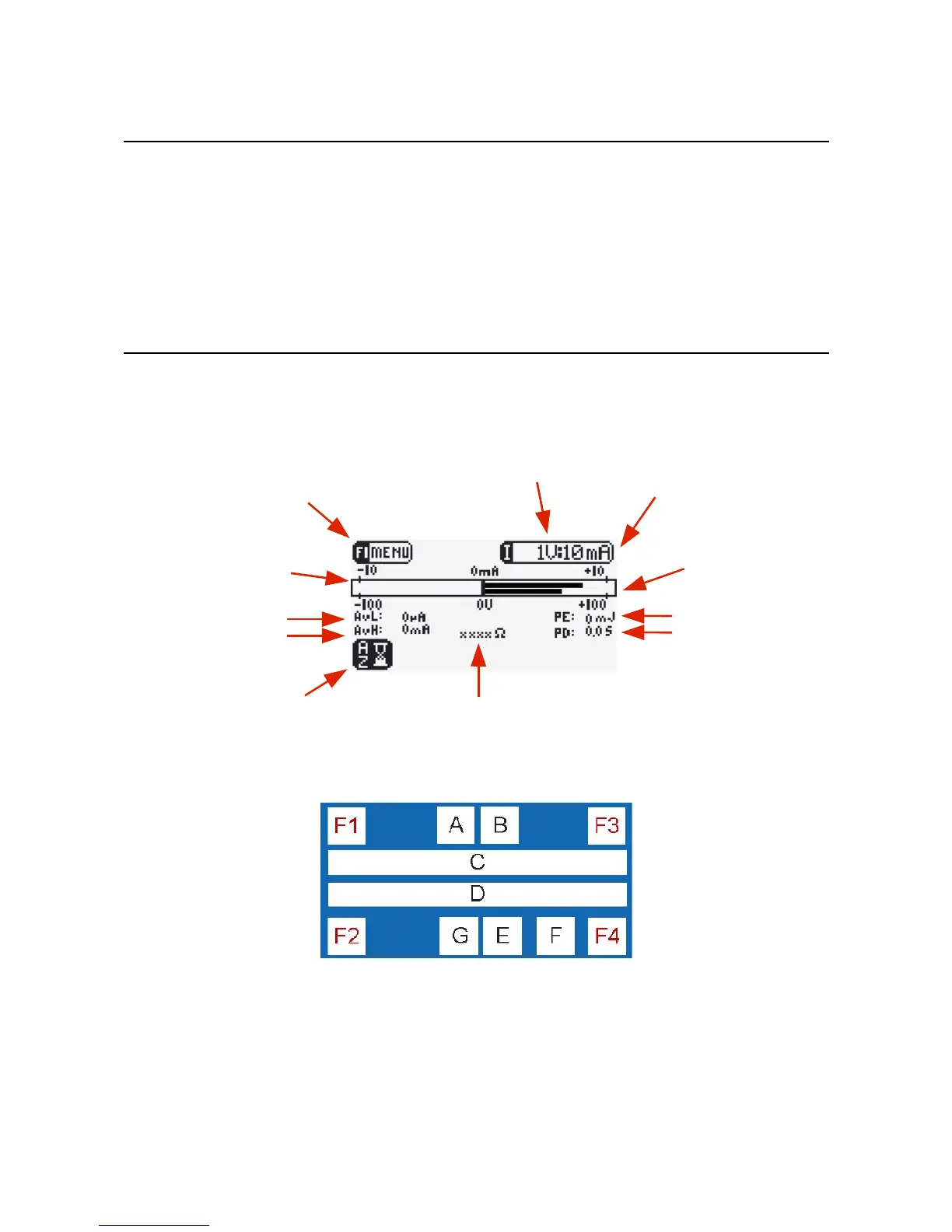
Figure 3.1 DS5 Main Operating Screen Display
Main Operating Screen Components & Icons
Figure 3.2 Main Operating Screen Zones
The main operating screen is divided into 10 zones which are used dynamically under different conditions.
Zones F1 and F2 are generally used to indicate functions for the F1 and F2 keys, while the F3 and F4 zones
tend to be used for purely informative purposes (although they are used to indicate the scroll up and scroll
down functions of F3 and F4 in the Options Menu). Zones A to G display various icons, text and graphs
which are fully described in Table 3.1.
Digitimer Ltd. 25 of 52 Copyright © 2009
F1/Menu Icon
Input Voltage Range (shown set to ±1V)
Output Current Bar Graph
(upper bar)
Average Low Level Current
Average Pulse (High)
Output Current
Output Impedance
Pulse Energy
Pulse Duration
Output Current
Range (shown set to ±10mA)
Output Voltage Bar Graph
(lower bar)
F2/Autozero icon (flashing)