DS5 Isolated Bipolar Constant Current Stimulator DS5 Operator's Manual 5.0
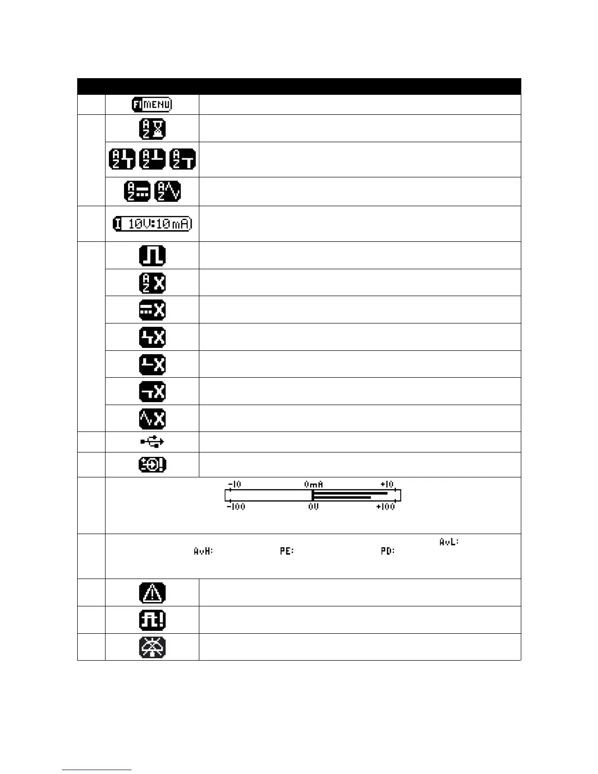
Area Icon/Display F-Key Allocation or Display Icon Meaning
F1
Pressing F1 opens the “Options Menu”.
F2
Flashing when Autozero required after timeout period.
Autozero not possible due to +ve and -ve pulses on the input (left).
Autozero not possible due to +ve pulses on the input (centre).
Autozero not possible due to -ve pulses on the input (right).
Autozero not possible due to an excessive DC offset on the input (left).
Autozero not possible due to oscillations on the input (right).
F3
Iconic display of the following adjustable DS5 settings:
Input Voltage Range:- ±1V, ±2.5V, ±5V or ±10V (shown)
Output Current Range:- ±10mA (shown), ±25mA or ±50mA
F4
Output Enabled:- Stimulation can proceed.
Output Disabled:- Autozero operation is required.
Output Disabled:- An initial DC stimulation >±10µA would result.
Output Disabled:- +ve and -ve pulses resulting in current peaks >400µA present.
Output Disabled:- +ve pulses resulting in current peaks >400µA present.
Output Disabled:- -ve pulses resulting in current peaks >400µA present.
Output Disabled:- Oscillation above +400µA or -400µA (peak) present.
A
Symbol when USB link with a computer is established.
B
Input Over Voltage Warning:- The three icons shown are used to indicate the polarity
of the excessive input voltage.
C
Twin horizontal bar graphs illustrate the output current (upper display) and the output voltage. The scaling of
the output current graph is adjusted when the output current range is changed.
D
Numerical display of the four limited parameters:- Average Low Level (baseline) Current ( ), Average High
Level (Pulse) Current ( ), Pulse Energy ( ) and Pulse Duration ( ). If any of these are exceeded,
the stimulator output is disabled and the parameter(s) responsible will be indicated by an arrow, exclamation
mark as well as an audible warning. This area is also used to display the patient impedance (ohms).
E
Warning symbol indicating that one or more output limits has been disabled.
F
Out of compliance warning (i.e the current requested cannot be provided due to
limitations of the compliance voltage).
G
Audio Off: - The audible information beep has been disabled.
Table 3.1 Main Operating Screen Components and Icons
Digitimer Ltd. 26 of 52 Copyright © 2009