DS5 Isolated Bipolar Constant Current Stimulator DS5 Operator's Manual 5.0
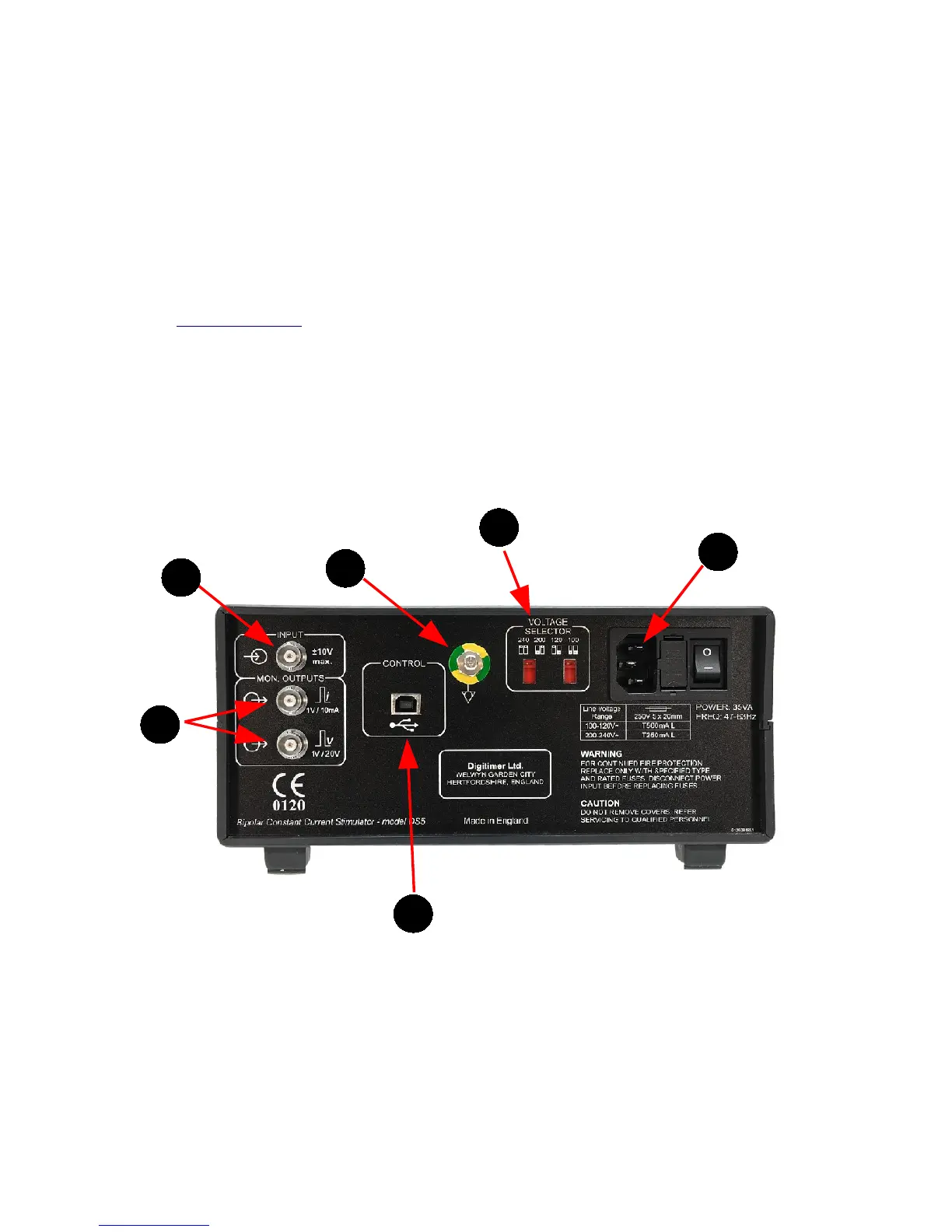
Rear Panel Components
1. Input - BNC Socket for a bipolar voltage input. Full scale voltage is switchable between ±1V,
±2.5V, ±5V and ±10V
2. Mon. Outputs - Monitor outputs providing output voltages that are proportional in shape to the
stimulus current (expressed as 1V/10mA) or voltage (expressed as 1V/20V). These outputs are
ground referenced and isolated from the patient.
3. Control - Type B USB socket providing a USB interface COM port to link the DS5 to a remote
personal computer running Windows 2000 or Windows XP. This socket allows for future updates to
the DS5 firmware, as well as control of DS5 settings via the DS5 User Interface Software (refer to
Chapter 4, Annex 2 BEFORE connecting). Only the USB cable supplied with the DS5 should be used
in this socket.
4. Mains Inlet, Mains Fusing and Power Switch Combination - NOTE - Power supply cord must
contain, and use, an Earth/Ground conductor.
5. Potential Equalisation Connector - Earth/Ground reference for unit and bonding point. This is
to be used when the earth/ground conductor in the mains cord of all units in use cannot be relied
upon or is not available.
6. Voltage Selector – The DS5 should be set to the appropriate mains supply voltage before the
stimulator is switched on.
Figure 2.2 Rear Panel Components of the DS5 Stimulator
Rear Panel Symbols
The rear panel of the DS5 has several symbols which the operator should become familiar with before
starting to use the stimulator.
Digitimer Ltd. 21 of 52 Copyright © 2009