12 www.dimplex.com
Electrical Installation
Installation
120V Installation—Wall Switch
!
NOTE: Use a single pole, single throw (On/Off) wall
switch that is rated for a minimum of 15 amps.
1. Cut the wire to an appropriate length.
2. Connect the black L1 wire from the unit to the live
wire from the main power through the wall switch,
ensuring all live connections are connected with a
wire connector.
3. Connect the white N wire from the unit to the neutral
wire from the power supply with a wire connector.
4. Terminate the yellow L2 wire from the replace with a
wire connector.
5. Connect the green G wire from the unit to the ground
wire from the power supply with a wire connector
or attach the grounding wire to the cover with the
provided grounding screw, by placing the wire in
between screw and lock washer and tighten.
6. Ensure all wire connections are tight and that wires
are secured a with wire ties and do not protrude past
the ame panel, so as not to be visible after nal
installation.
120 V Hardwire Installation
1. Cut the wire to an appropriate length.
2. Connect the black L1 wire from the unit to the live
wire from the power supply with a wire connector.
3. Connect the white N wire from the unit to the neutral
wire from the power supply with a wire connector.
4. Terminate the yellow L2 wire from the replace with a
wire connector.
5. Connect the green G wire from the unit to the ground
wire from the power supply with a wire connector
or attach the grounding wire to the cover with the
provided grounding screw, by placing the wire in
between screw and lock washer and tighten.
6. Ensure all wire connections are tight and that wires
are secured with wire ties and do not protrude past
the ame panel, so as not to be visible after nal
installation.
WARNING:
The installation of the electric replace must comply with the applicable Local and/or National Electrical Codes
and utility requirements.
Use the appropriate wire to meet local and national electrical codes for rated power consumption.
CAUTION: A dedicated, properly fused 15 Amp circuit is recommended, rated for the appropriate voltage (120V,
240V). A dedicated circuit will be required if, after installation, the circuit breaker trips or fuse blows on a regular
basis when the heater is operating. Additional appliances on the same circuit may exceed the current rating of
the circuit breaker.
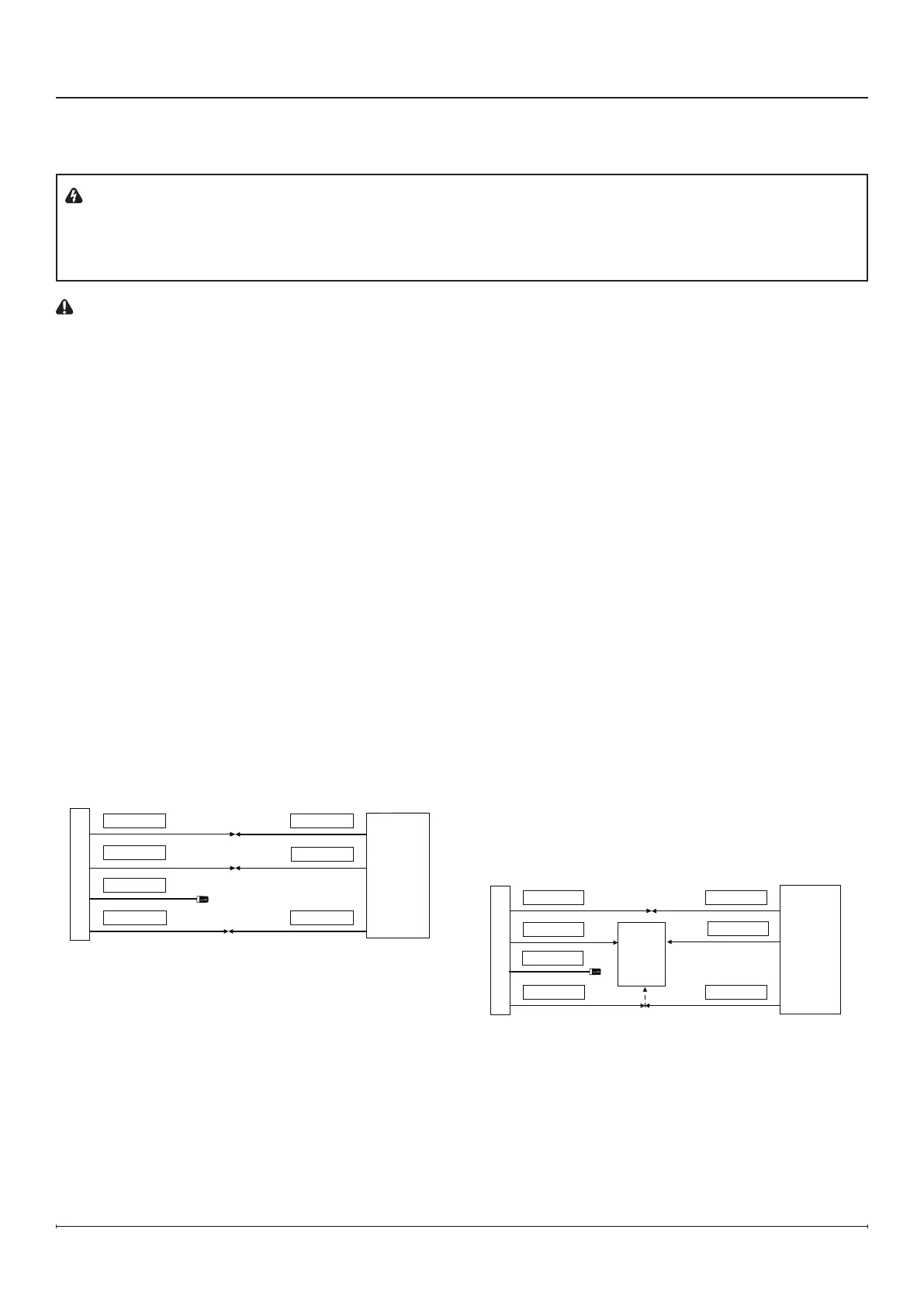
Figure 6
120 V
POWER
SUPPLY
(BREAKER
PANEL)
240 V
POWER
SUPPLY
(BREAKER
PANEL)
YELLOW- L2
120 V Hardwire Installation
Figure 7
120 V
POWER
SUPPLY
(BREAKER
PANEL)
WALL
SWITCH
YELLOW- L2
120 V Wall Switch Installation