3590EKR, 3590EXP, 3590EXT, 3590 EBOX, CPWE, CPWET series indicator E-AF03_05.01_14.07_EN_T.doc
2.3 CONNECTION OF LOAD CELLS TO INDICATOR
The load cell has a digital output with an RS-485 interface (4-wire). In regards to the power supply, it needs an external
continuous voltage (CC).
To configure the cells it is necessary to go to the nuM.SCA >> 1 SCALE >> CELtyP step and then choose the type of cell:
AnALoG Cells type analog
dGX Cells type digital DGX
rCd Cells type digital RCD
CCi Ad Cells type digital CCI AD
rC3d Cells type digital RC3D
C16i Cells type digital C16i
WWS Cells type digital WWS
(!)AnALoG
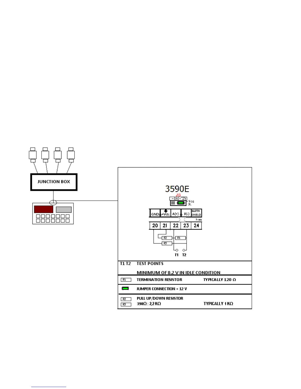
In most cases in order to avoid to make a jumper connection between the cells one uses a junction box which is connected
to the indicator on the terminals dedicated to the 485 port. In between the terminals one needs to apply 2 Pull Up
resistances and a termination one in order to have a minimum 0,2 V voltage between A(+) and B(-) (terminals 22 and 23):
Since each cell uses a filter different than the default one, the functioning speed varies from one load cell type to another.
For the length and section of the connection cables, see the section “MAXIMUM LENGTHS ALLOWED FOR THE
CABLES”
 Loading...