3590EKR, 3590EXP, 3590EXT, 3590 EBOX, CPWE, CPWET series indicator E-AF03_05.01_14.07_EN_T.doc
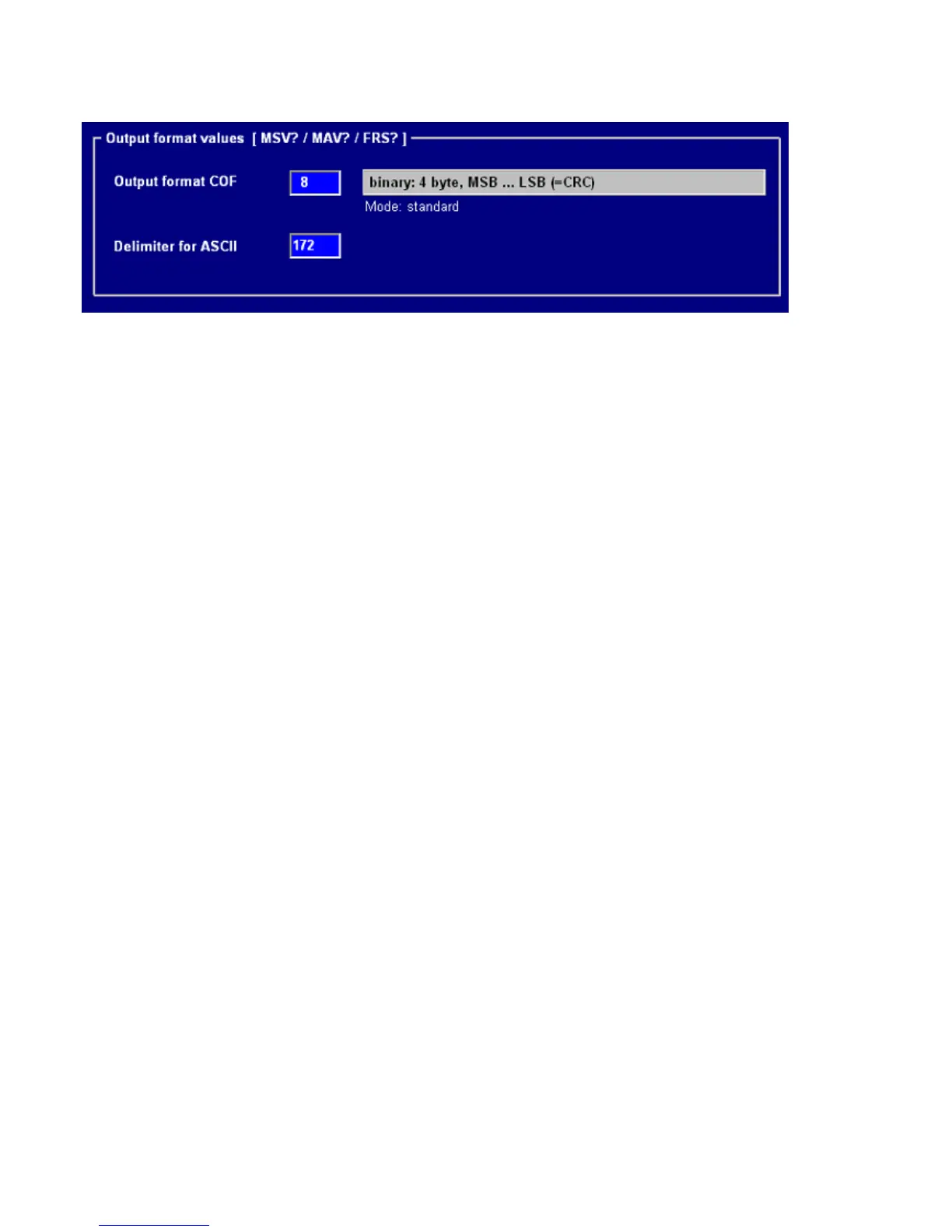
By entering in Parameters >> Communication it is necessary to insert the COF format and the ASCII delimitation as
shown in figure:
Once the type of cell is chosen (SEE 2.3) one needs to enter the number of cells used, and the indicator shows: Cells
Number.
After having chosen the number of cells the indicator automatically enters in the step
SEt.485 Set 485 Address cells
Enter the number of the cell and the relative serial number one after the other and at the end press C. The following
appears:
Snd.CFG Send configuration?
Press Enter and the setting from the indicator is finished.
2.3.2 RCD DIGITAL CELL CONNECTION
Once the type of RCD cell has been chosen, one should enter the number of cells used, the indicator shows: Cells
Number.
After having chosen the number of cells, the indicator automatically enters in the step
SEt.485 Set 485 Address cells
Enter the cell number and the relative serial number one after the other,and at the end,press C. The following appears:
Snd.CFG Send configuration?
Press Enter and the setting from the indicator is finished.
For the connection of the RCD cells to the indicator, a junction box is necessary, which is connected to the indicator
through 485, also necessary two bias resistors. (SEE SECTION “RS 485 CONNECTION)
 Loading...