13
IP1950EN - 2013-09-13
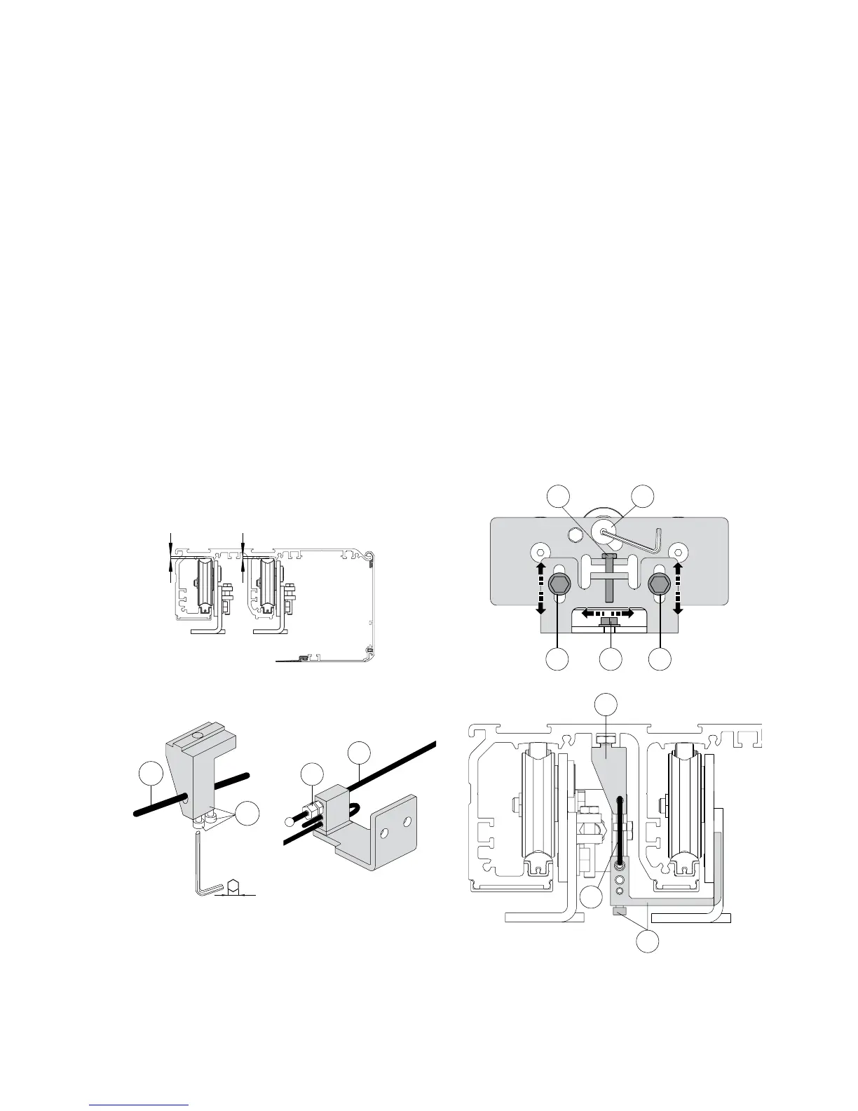
Make sure that the central wheel [d] is adjusted as illustrated in the diagram.
Fix the door wing to the carriage with screws [a].
The outer wheel of the carriage must not protrude beyond the dimension of the door wing.
Adjust the horizontal position of the door wing in accordance with the measurements indicated in
diagram VALOR 2 +2 for four door wing automations, VALOR 1 +1 RH for right-hand opening automa-
tions and VALOR 1 +1 LH for left-hand opening automations. Secure the adjustment with screws [a].
Loosen screws [b], adjust the vertical position of the door wing by means of screw [c] and fix the
adjustment with screws [b].
Check, by moving the door manually, that the movement is free and without friction and that al
the wheels rest on the guide.
Proceed as follows to adjust the overlap of the door wings:
- Place the door in the closed position.
- Hold the external door wing in the closed position.
- Loosen [g] and move the door wing, increasing or decreasing the overlap.
- Tighten [g].
Adjust the tension of the cables by means of adjuster [e], loosening the locking nut.
Correctly tension the cable, then block it with the locking nut.
a
c d
b b
e
f
e
g
f
max 0,5 mm
max 0,5 mm
5.6 VALOR T wings installation and adjustment
g
f
3 mm