EasyManua.ls Logo

DITEC ENTREMATIC HA9 User Manual

DITEC ENTREMATIC HA9
58 pages
To Next Page IconTo Next Page
Page #1 background imageLoading...
Page #1 background image
info.ditec.ca@entrematic.com
www.ditecentrematic.ca
info.ditec.us@entrematic.com
www.ditecentrematic.us
HA9 Manual V. 1.3
1019956
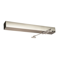
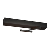
DITEC HA9 LOW ENERGY
SWING OPERATOR
Installation & Instruction Manual
READ AND FOLLOW ALL INSTALLATION INSTRUCTIONS CAREFULLY!
FAILURE TO DO SO MAY RESULT IN PERSONAL INJURY OR PROPERTY DAMAGE!
This product is to be installed on the interior side of the door.
Install only on a properly operating and balanced door. A door that is operating improperly could cause severe
injury. Before installing the operator, have qualified service personnel make repairs to cables, and other hardware.
Before installing the operator, remove or make inoperative, all locks (unless mechanically and/or electrically
interlocked to the power unit), all activation units and accessories that may be connected to the door.
A commercial/industrial door operator that has exposed moving parts capable of causing injury to persons or
employs a motor deemed indirectly accessible by virtue of its location above the floor shall include:
- Install the door operator at least 2.4m (8ft) or more above the floor, and/or
- If the operator must be installed less than 2.4m (8ft) above the floor, then exposed moving parts must be
protected by covers or guarding provided by the operator manufacturer.
The control unit MUST be located: (1) within the sight of the door, and (2) at a minimum height of 1.5m (5ft) above
the floors, landings, steps, or any other adjacent walking surface and (3) away from all moving parts of the door.
Install the Entrapment Warning Placard next to the control station in a prominent location if applicable.
To reduce the risk of injury to persons - Use this system only with pedestrian doors.
Do not connect the operator to a power supply until instructed to do so. Connection of the high voltage supply
should be done by a qualified professional and within the guidelines of the enforced local electrical codes.
HIGH VOLTAGE (INCOMING 115 VAC) WIRES AND LOW VOLTAGE WIRES CANNOT SHARE THE SAME
ACCESS HOLE. HIGH VOLTAGE WIRES MUST BE ROUTED AND SECURED AWAY FROM ALL LOW
VOLTAGE WIRES.
Entrematic Canada Inc. Entrematic USA Inc.
Toll Free: 1-877-348-6837 Toll Free: 1-866-901-4284

Questions and Answers:

DITEC ENTREMATIC HA9 Specifications

General IconGeneral
Motor Voltage24 V DC
DimensionsCheck the official documentation
Operating Temperature-20°C to +55°C
Maximum Current1.5 A
Power Supply230V AC, 50/60Hz
Opening SpeedAdjustable
Closing SpeedAdjustable
Safety FeaturesObstacle detection
Protection levelIP44
Protection DegreeIP44

Summary

General Safety and Installation Precautions

Critical Installation Safety Warnings

Mandatory safety instructions for installation to prevent injury or property damage.

General Information

Typical Installation Flow Chart

Step-by-step visual guide outlining the automatic door operator installation process.

Completed Door Installation Diagram

Illustrates the components and layout of a typical automatic swing door installation.

Replacement Parts Identification

Lists and identifies all available replacement parts for the HA9 operator.

Important Information and Safety Guidelines

Covers intended use, safety precautions, electronic interference, and environmental requirements.

Compliance Codes and Technical Specifications

Details applicable codes, standards, and technical specifications of the HA9 operator.

HA9 Operator Functionality Overview

Explains the operational principles of the HA9 swing door operator.

Control Unit HA9 Functions and Features

Describes the various functions and operational modes of the HA9 control unit.

Extension Unit EXU-SI Functions

Details the functions and capabilities of the EXU-SI standard extension unit.

Extension Unit EXU-SA Functions

Outlines the features and functionalities of the EXU-SA optional extension unit.

Pre-Installation Checks and Preparation

Covers essential steps and considerations before commencing the installation process.

Door and General Safety Tips

Provides tips on door edge safety, security, wiring, and entrapment prevention.

Consideration of Surroundings and Tools

Addresses environmental factors, ADA requirements, and necessary tools for installation.

Operator Type and Handing Identification

Explains how to determine the operator type (Push/Pull) and door handing (Left/Right).

Operator Installation

Header Box Pre-Mounting Instructions

Steps for disassembling and preparing the header box before mounting.

Push Header Installation Guide

Detailed instructions for mounting the header box for push-type door installations.

Pull Header Installation Guide

Instructions for mounting the header box for pull-type door installations.

Double Egress Header Configuration

Guidance for installing the header for double egress doors with both push and pull operators.

Electrical Connection Procedures

Steps for safely connecting the incoming mains power to the operator unit.

Changing Unit Configuration (Push to Pull)

Procedure for reconfiguring the operator from push to pull requirements.

Motor/Gearbox Reinstallation

Instructions for correctly reinstalling the motor/gearbox assembly onto the mounting studs.

Arm Installation

Push Arm Components and Configurations

Identifies main components of the push arm and standard configuration.

Alternate Push Arm Configuration (Option 2)

Details an alternative push arm setup for installations with clearance issues.

Push Arm Installation Procedure

Step-by-step guide for installing the push arm onto the operator and door.

Pull Arm for Pull Application Setup

Describes the setup and mounting for the pull arm in pull-type applications.

Pull Arm Installation: Marking Positions

Guides on marking closed and open positions for accurate pull arm installation.

Pull Track Fitting and Adjustment

Instructions for fitting the pull track and making necessary adjustments for optimal operation.

Attaching the Pull Arm Assembly

Final steps for attaching the pull arm to the roller shaft and ensuring proper alignment.

Control Units

HA9 Control Unit Overview

Details the main HA9 control board, arm system selection, and configuration settings.

Extension Unit EXU-SI/EXU-SA Installation

Instructions for installing EXU-SI and EXU-SA extension units onto the HA9 control unit.

EXU-SI Extension Unit Functions and Connections

Explains the functions, inputs, and connections for the EXU-SI standard extension unit.

EXU-SA Extension Unit Functions and Sensors

Describes the functions, inputs, and sensor connections for the EXU-SA optional extension unit.

Operator Tuning

Back Check and Latch Adjustment

Procedure for adjusting the door's back check and latching points for optimal performance.

Micro Switch Adjustment for Lock Kick

How to adjust the micro switch for the lock kick function for proper closing and latching.

Sync Cable for Double Doors Setup

Instructions for connecting and configuring the sync cable for synchronized double door operation.

Double Door Parameter Settings

Defines parameter settings for MASTER and SLAVE operators in double door configurations.

Auto-learn Procedure for Door Settings

Automatic learning process to set back-check, latch-check, and open positions.

Learn Button Functions (Single/Double Push)

How to use the Learn button for delayed or direct opening during auto-learn.

Double Door Learn Button Operation

Specific procedures for learning double door systems using the Learn button.

Advanced Back- and Latch-Check Tuning

Advanced method for setting back-check and latch-check parameters.

Reverting Back- and Latch-Check to Defaults

Procedure to reset back-check, latch-check, and open position to factory default settings.

General Operator Adjustments

Covers adjustments for hold open time, opening/closing speed, and activation units.

Spring Pre-tension (SPTE) Adjustment

Guide to reducing or increasing the spring pre-tension for proper door closing force.

Activation Units & Accessories

Connecting Activation Units and Sensors

Wiring diagrams and instructions for connecting activation sensors and accessories.

Parameter Adjustment Procedure

Steps for adjusting operator parameters using the Learn button and group selection.

Advanced Settings

Overhead Presence Detection (OPD) Monitoring Setup

Configuration and recommended settings for the Overhead Presence Detection sensor.

Lock Kick Function Configuration

How to configure the lock kick function for enhanced security during closing.

Lock Unlock Function Configuration

Setting up the lock unlock function based on door position.

Installation Wrap Up

Additional Safety Sensors and Devices

Information on integrating safety sensors, knowing act devices, and jamb switches.

Header Cover Installation

Instructions for installing the header cover after all adjustments are completed.

Safety Decals Application Guidelines

Guidance on properly applying safety and instruction decals to the door.

Safety Sticker Placement Examples

Visual examples showing the correct placement of safety stickers on doors.

Troubleshooting

Common Door Operation Faults and Remedies

Lists common problems like door not opening/closing and their solutions.

Error Indication Codes and Solutions

Explains error codes indicated by the LED flash frequency and their corresponding remedies.

Service/Maintenance

Regular Service and Maintenance Schedule

Guidelines for regular inspections and scheduled maintenance by qualified technicians.

Manufacturer Information

Manufacturer and Shipping Addresses

Contact information for Entrematic Canada and USA, and technical service department.

Applicable Codes and Standards Summary

Lists the codes and standards the HA9 operator complies with.

Related product manuals