Entrematic Canada Inc.
Toll Free: 1-877-348-6837
info.ditec.ca@entrematic.com
www.ditecentrematic.ca
Entrematic USA Inc.
Toll Free: 1-866-901-4284
info.ditec.us@entrematic.com
www.ditecentrematic.us
1.12 Consideration of Surroundings
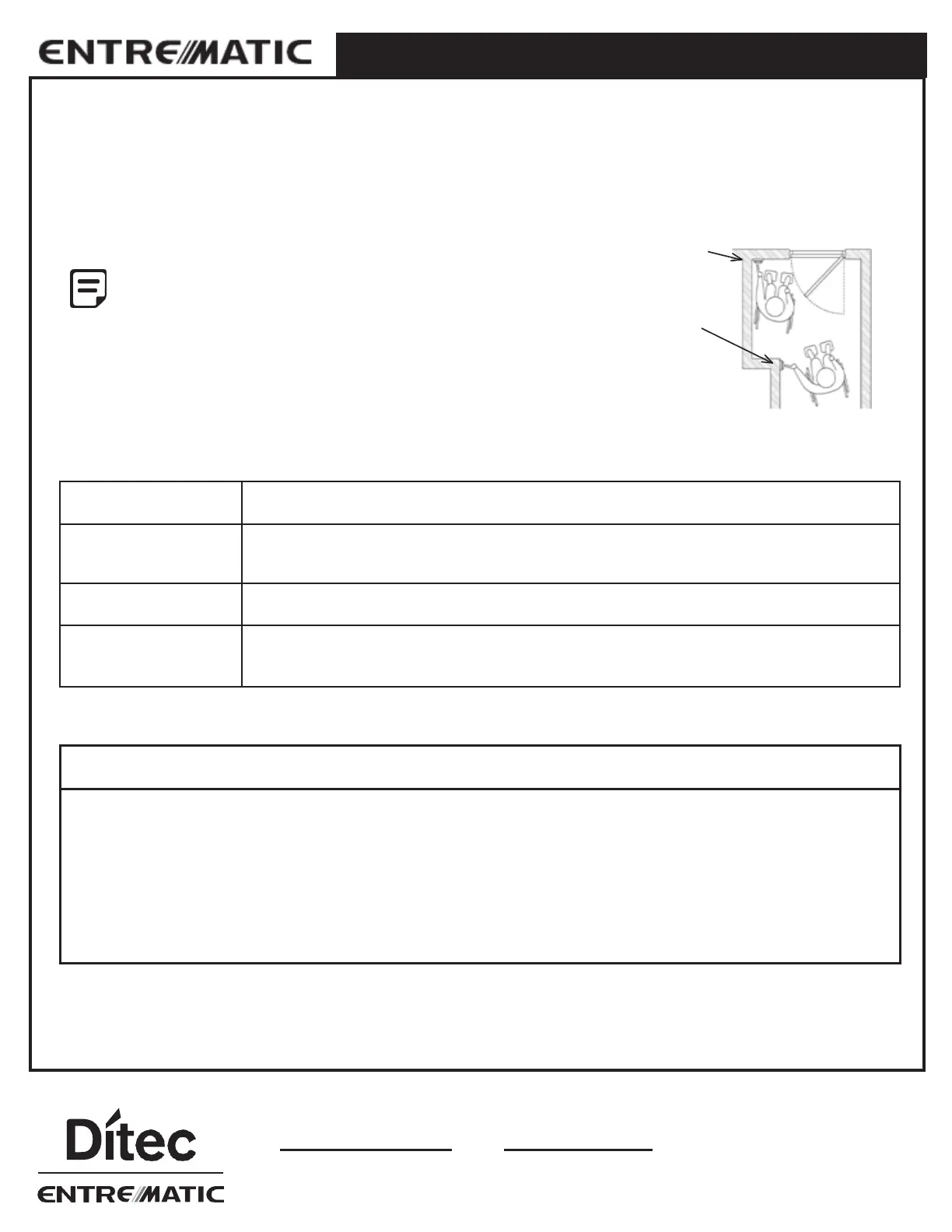
Floor Space Requirements for Wheel Chair Maneuvering - Americans with Disabilities Act (ADA)
The owner may request the activation device location; however, the press switch must be in view of the door and not directly
on the door or frame. Please refer to ANSI 117.1 Safety Code for further guidelines on switch requirements.
Position# 1
Minimum 2' (610mm)
Activation switches shall be at minimum height of
36" (914.4mm) and maximum height of 48"
(1219mm) from finished floors or as specified by
a local Authority Having Jurisdiction.
Individual who uses wheelchair needs a minimum
of 48” clearance to the door swing for doors in
sequence application.
From door latch
Position# 2
Minimum 5' (3048mm)
from door face
External and Internal Factors
Door must move easily open and close (latch) without excessive force; weather stripping and
Threshold must not interfere with door movement.
For out swing (Push) doors, the reveal must be within the range of 0" to 14" (356mm). For in
swing (Pull) doors, 0" to 2 ⅜” (60mm) for special reveals is allowed
-
for all others consult
factory.
When installing on a door in a strong wind condition area, special adjustments should be made
to the doorstop position and controller adjustments.
Check that the electrical feed, all conduits, and electrical junction boxes (for push plates or
other activation devices, if required) are correctly located in accordance with final approved
shop drawings and within the guidelines of the enforced local electrical codes.
Required Tools for Installation:
• Torx, T10
• Allen Wrench Set
• Nut Driver, 5mm
• Screwdrivers: Flat, Philip, 5/16" Hex. Nut
• Power Drill and Drill Bits
• Additional Fasteners Depending Surface
• Center Punch
• Tape Measure
• Silicone Sealant
• Hand Saw/ Power Saw