Entrematic Canada Inc.
Toll Free: 1-877-348-6837
info.ditec.ca@entrematic.com
www.ditecentrematic.ca
Entrematic USA Inc.
Toll Free: 1-866-901-4284
info.ditec.us@entrematic.com
www.ditecentrematic.us
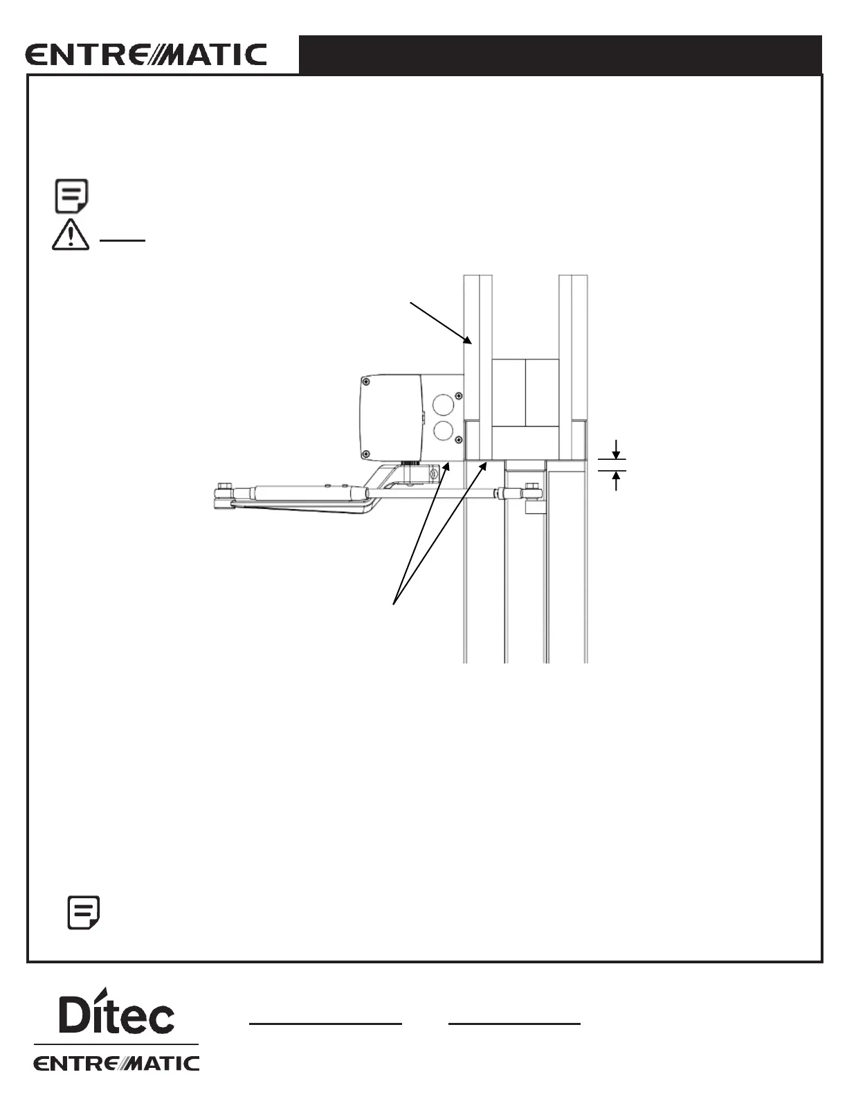
2.2 Push Header Installation
The Header Box on push installations is mounted flush to the bottom of the door frame. It may require solid backing
material to compensate for the thickness of the door frame.
Holes can be made anywhere in header to secure. All holes MUST be drilled into substantial
support (studs, blocks, framing, etc.). This diagram may not reflect your installation.
Do Not use Drywall Screws or Hollow Wall Anchors to mount the back plate / header.
Before fastening header box to the door frame, dry fit header by positioning the backer plate flush to the bottom of the
door jamb and the previously marked spindle center line is 8¼“ (210mm) from the door hinge/pivot.
1. Mark locations to drill frame to match the predrilled access holes for high and low voltage wires and mounting holes. If
the holes are not at a convenient location, you can drill the backer plate to suit.
2. Anchor the back plate to the wall with minimum of six (6) - #14 x 1" Pan Quad Type A screws (provided). You may
need to provide other screws if your installation requires it. The locations of the screws on the header are application
dependent but (2) of the screws must fasten the back plate directly to the door’s vertical jambs on the hinge side.
3. Add additional screws to fasten the header back plate to the door frame approximately 12" to 16" (305mm to
406mm) apart. The header must be strong enough to support 200 lbs. (90kg).
For most applications, the header is equal to door opening plus 3" (76mm). This allows for a 1½"
(38mm) space on either side of the Header Box. However, it MUST be installed 1½" (38mm) from hinge
side for all Push installations, regardless if header is sized appropriately to anchor the header box
properly to the frame.
2.0 OPERATOR INSTALLATION