Entrematic Canada Inc.
Toll Free: 1-877-348-6837
info.ditec.ca@entrematic.com
www.ditecentrematic.ca
Entrematic USA Inc.
Toll Free: 1-866-901-4284
info.ditec.us@entrematic.com
www.ditecentrematic.us
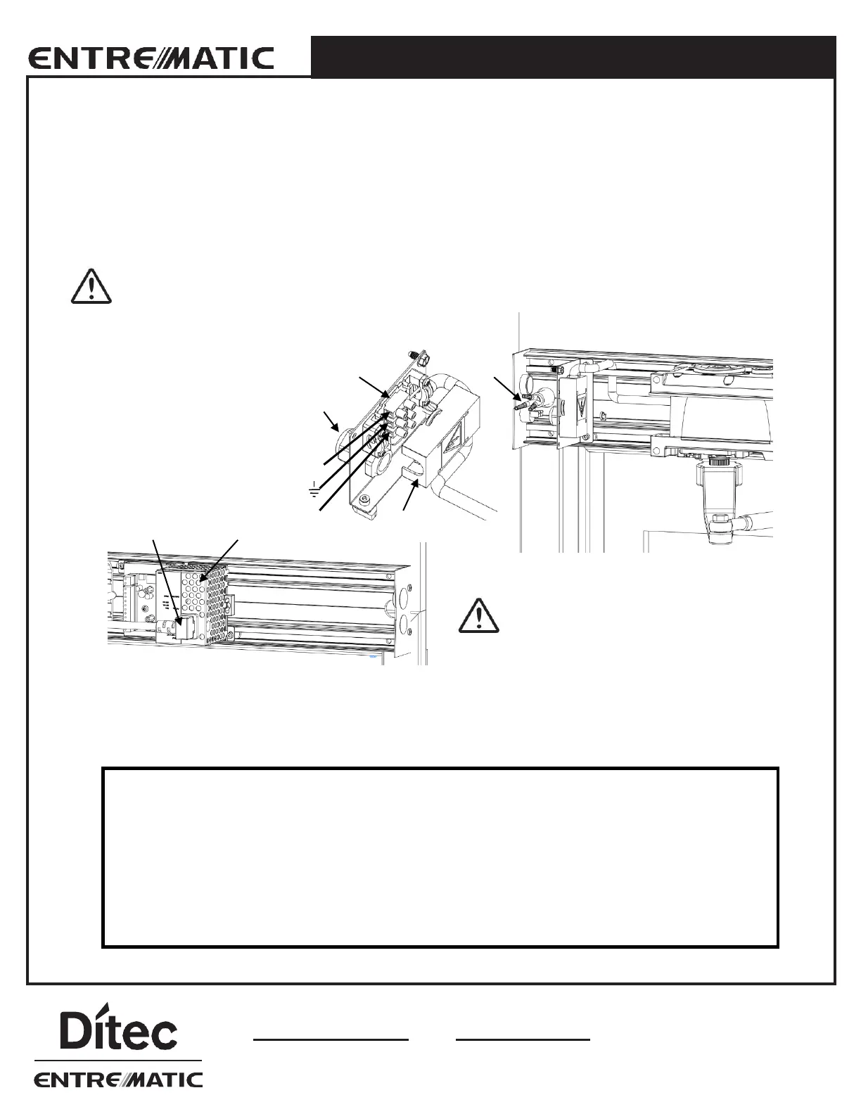
2.5 Electrical Connection
The incoming mains, which is a single phase 50/60 Hz AC voltage between 100 V -10% and 240 V+10% fuse 10 AT, is
connected in the mains connection unit.
1. Remove the protective lid (2).
2. Connect the incoming mains power (4) through the strain relief (3) to the connection block (1) as shown in the
illustration below.
3. Put the protective lid (2) back in place.
Installer must properly ground door package! Improper grounding can lead to risk of personal
injury.
1
Mains connection block
2
Protective lid
3
Strain relief
4
Incoming mains power
5
Mains connection
6
HA9
The mains connection (5) must remain
isolated until the wiring is completed. Then
connect to the HA9 (6).
The control board settings have been pre-set prior to shipment. It will be necessary for the door operator to be functional
while adjustments and settings are made. Power up the unit, push an activating device and check to make sure that the
spline pinion drive rotates in the correct direction. Keep all wires away from moving parts and sharp edges that may cut into
the outer casing of the wires.
THE GROUND WIRE FOR THE INCOMING HIGH VOLTAGE POWER AND THE SYSTEM GROUND WIRE
CANNOT SHARE THE SAME GROUNDING STUD. GROUND THE INCOMING HIGH VOLTAGE
ACCORDINGLY.
• Installation of any extra wiring for controls or accessories into the header unit shall be secured and away
From any moving parts.
• If the motor is not plugged into the circuit board, there is no resistance against the spring when manually
opening the door. The door or arm will close very quickly if opened.
• If an electrical access hole is added or knocked-out of the end plates, code approved electrical transfers
must be used. Hole cannot be knocked out and unfilled.
2.0 OPERATOR INSTALLATION