DOD Technologies, INC • 675 Industrial Dr. Bldg. A • Cary, IL 60013 • Phone (815) 788-5200 • Fax (815) 788-5300
the green wire (+) and the blue wire (-). Do this carefully to avoid a short between the DMM probes and
a blown fuse. The voltage at each block should be greater than 5.3 VDC.
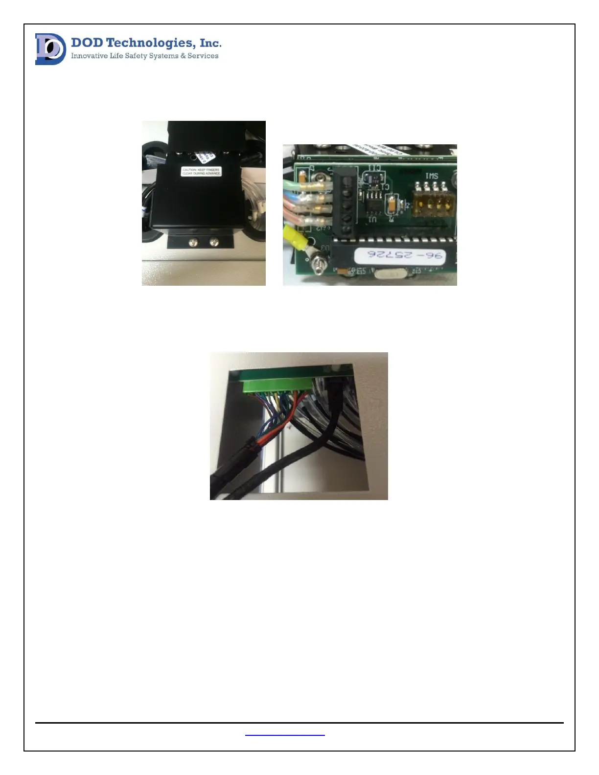
If the voltage is below 5.3VDC measure between the red (+) and the black (-) located on the green
connector at the back of the analyzer (see image below). The voltage here should also be greater than
5.3 VDC.
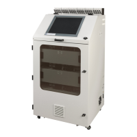
If the voltage at the green connector is below the required voltage, continue down to the pump panel and
measure the voltage at the related analyzers fuse holder, red wire (+) and black terminal block (-)(see
image below). Also verify none of the red lights are on, if one is on, this indicates a blown fuse and it must
be replaced.