DOD Technologies, INC • 675 Industrial Dr. Bldg. A • Cary, IL 60013 • Phone (815) 788-5200 • Fax (815) 788-5300
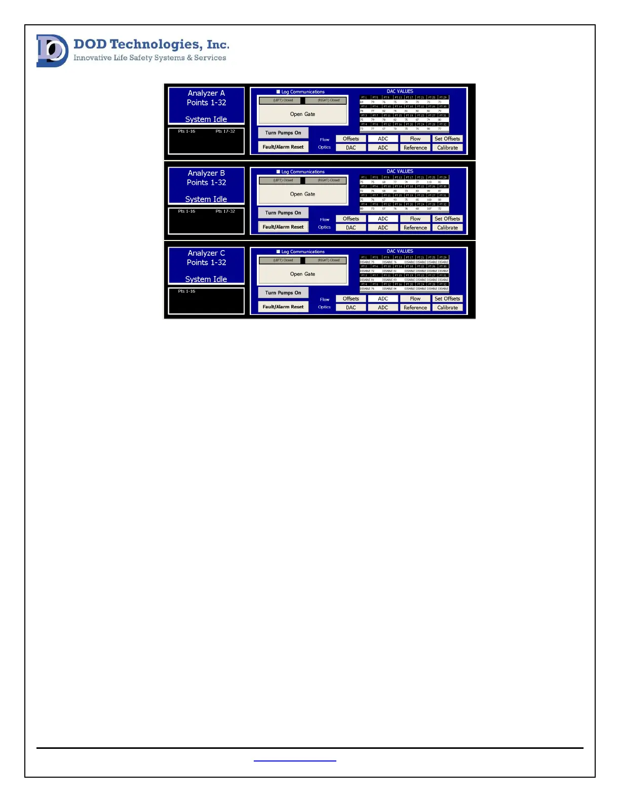
Select the DAC button for each analyzer and look for any “0” values or “255” values. Also, press the ADC
button for each analyzer and look for any “0” values or “4095” values. If any point has these DAC or ADC
values follow these steps first.
1. Power Cycle the Analyzer
2. Open the Gate
3. Rotate the Chemlogic Cassette so there is a fresh tape surface between the gate
4. Close the Gate
5. Press Calibrate
If the results persist move on to the power and communication verification steps.
Power Verification Procedure:
The following tools will be needed to perform the Optic System Power Verification.
1. Digital Multi-meter
2. #2 phillips screwdriver
3. #1 standard screwdriver
First, remove the cover for the optic block that is not working properly (see image below). When the
cover is removed the power wires will be accessible. Using the DMM, measure the DC voltage between