EasyManua.ls Logo

DOD CL96 - User Manual

DOD CL96
44 pages
Print Icon
To Next Page IconTo Next Page
Loading...
DOD Technologies, INC • 675 Industrial Dr. Bldg. A • Cary, IL 60013 • Phone (815) 788-5200 • Fax (815) 788-5300
DC-ITD-CL96Servicemanual
www.dodtec.com
Innovative Life Safety Systems & Services
CL96 Gas Detection System
Technical Service Manual
Revision 16.11

Questions and Answers

  • P
    powellricardoSep 19, 2025
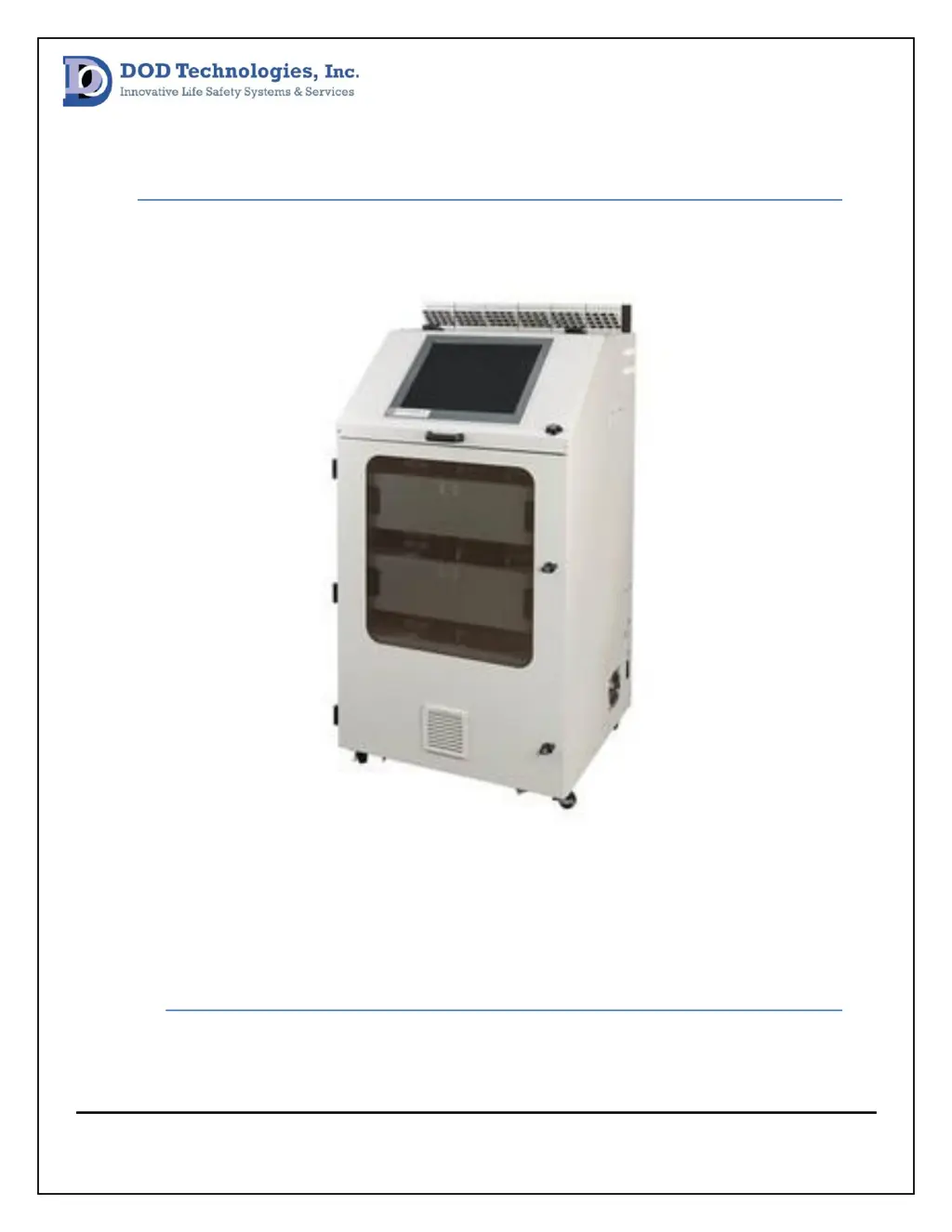
    How to troubleshoot Output Module Communication Error on DOD CL96?
    • C
      croseSep 22, 2025
      If the DOD Gas Detectors unit displays 'Output Module Communication Error', it indicates an I/O module communication issue with the PC. Refer to I/O Verification Procedure.
  • J
    John HernandezAug 25, 2025
    What to do if DOD CL96 show Gas alarm Level 2?
    • E
      ericwebbAug 25, 2025
      If the DOD Gas Detectors indicate a Gas Alarm Level 2, it signifies a gas release exceeding Alarm Level 2. You should determine the release point.
  • A
    Anthony ScottAug 25, 2025
    What to do if DOD CL96 Gas Detectors show PLC Comm. Error?
    • T
      tiffany29Aug 26, 2025
      If the DOD Gas Detectors display a PLC Comm. Error, it indicates a communication issue between the PC and PLC. First, power cycle the CL96. If the issue continues, contact DOD Technologies, Inc.
  • H
    hjacksonAug 27, 2025
    What causes Modbus Comm. Failure in DOD CL96 Gas Detectors?
    • K
      Kelly MarquezAug 27, 2025
      If your DOD Gas Detectors unit displays 'Modbus Comm. Failure', there has been an interruption during the Modbus communication process. Try power cycling the unit. If the problem persists, contact DOD Technologies, Inc.
  • M
    Mrs. Catherine EllisSep 23, 2025
    What to do if DOD CL96 show Custom Output Module Failure?
    • L
      Luis McgeeSep 23, 2025
      If the DOD Gas Detectors unit displays 'Custom Output Module Failure', it means that the PC cannot communicate with the I/O modules. Refer to the I/O Verification Procedure.
  • R
    Robert AndersonSep 23, 2025
    What does Output Module Offline mean on DOD CL96?
    • N
      Nicholas CobbSep 23, 2025
      If the DOD Gas Detectors unit displays 'Output Module Offline', it means that the PC cannot communicate with the I/O modules. Refer to the I/O Verification Procedure.
  • A
    Andrea EatonSep 10, 2025
    What does Idle Timeout (Analyzer) mean on DOD Gas Detectors?
    • C
      christopher03Sep 12, 2025
      If the DOD Gas Detectors unit displays 'Idle Timeout (Analyzer)', it means that an analyzer was left out of analysis for a time frame that overlapped the time out setting. Check to see if a fault caused the CL96 to leave analysis and if not put the CL96 back into analysis.
  • M
    mistytaylorSep 12, 2025
    How to fix CL96 System Fan Failure on DOD Gas Detectors?
    • R
      Ryan DukeSep 12, 2025
      If the DOD Gas Detectors unit displays 'CL96 System Fan Failure', it means that fan on side panel has failed. Replace fan on CL96 side panel.
  • B
    Benjamin RodriguezSep 3, 2025
    How to troubleshoot Pyrolyzer Control Module Fault on DOD CL96?
    • B
      Bailey BakerSep 4, 2025
      If the DOD Gas Detectors unit displays 'Pyrolyzer Control Module Fault', it indicates a communication issue between the PC and pyrolyzer control modules. Verify the connection of communication modules, unplug and re-insert cables on communication module, power cycle CL96, and replace communication modules.
  • B
    bakersergioSep 1, 2025
    Why is the point disabled due to high background on DOD Gas Detectors?
    • K
      kristenjacobsonSep 1, 2025
      If the DOD Gas Detectors unit displays 'Point Disabled Due to High Background', it means a point has been disabled because of a high background. Press the Verify Optics button in the Load Tape screen.

Summary

Preventative Maintenance Procedures

Optics System Maintenance

Procedures for maintaining the optic system of the CL96 gas detection system.

DAC Verification Procedure

Verifying DAC values within the optic system for proper calibration.

Background Verification Procedure

Verifying background values for each point in the system screen.

Flow System Procedures

Pressure Sensor Calibration

Calibrating pressure sensors by checking voltage offsets for atmospheric pressure.

Point Flow Check with Flowmeter

Performing an additional flow check at each point using a flowmeter.

Exhaust Integrity Check

Checking the exhaust line for each pump to ensure correct exhaustion.

System Flow Balance

Tape Advance System

Advance Distance Verification

Verifying the distance of each tape advance is within specifications.

Micro Switch Verification

Verifying the tightness of micro switches for gate position detection.

Gate Assembly Maintenance

Lubricating Gate Assembly

Lubricating gate assemblies for efficient operation and motor longevity.

Power System Verification

DC Voltage Verification Procedure

Detailed steps to verify DC voltages from power supplies.

System Inspection Procedures

Vibration Damage Inspection

Checking pump panel wiring and tubing for vibration-induced damage.

Wire Inspection

Visually inspecting wiring and tightening terminal block jumpers.

Troubleshooting and Fault Resolution

Optic Cleaning Procedure

Procedure for cleaning optic channels when specific error messages appear.

Optic System Troubleshooting

Optic System Power Verification

Communication Verification

Gate Fault Procedure

Flow Check Procedures

Flow Communication Verification

Verifying communication between flow system boards and the PC.

Flow Path Verification

I;O and Configuration

I;O Verification Procedure

Troubleshooting steps for output module communication errors or failures.

Device Configuration Settings

Verifying and adjusting device configuration settings for analyzers.

Hardware Replacement

Optic Block Replacement

Steps to replace a CL96 optic block, including tools needed.

Pump Replacement

Steps and tools required to replace a CL96 pump.

Appendices

Appendix A: Control Wiring Diagram

Detailed wiring diagram for the CL96 control system.

Appendix B: Pump Panel Wiring Diagram

Wiring diagram specific to the CL96 pump panel.

Appendix C: Analyzer Wiring Diagram

Wiring diagram for the CL96 analyzers.

DOD CL96 Specifications

General IconGeneral
BrandDOD
ModelCL96
CategoryGas Detectors
LanguageEnglish