DOD Technologies, INC • 675 Industrial Dr. Bldg. A • Cary, IL 60013 • Phone (815) 788-5200 • Fax (815) 788-5300
Innovative Life Safety Systems & Services
For the optic system to communicate properly the addresses on each block must be set correctly. A 32
point analyzer should be addressed 1 through 8 and a 16 point analyzer should be addressed 1 through
4. Using the optic block map on each analyzer and the chart below, with the optic covers removed,
confirm the addresses are correct.
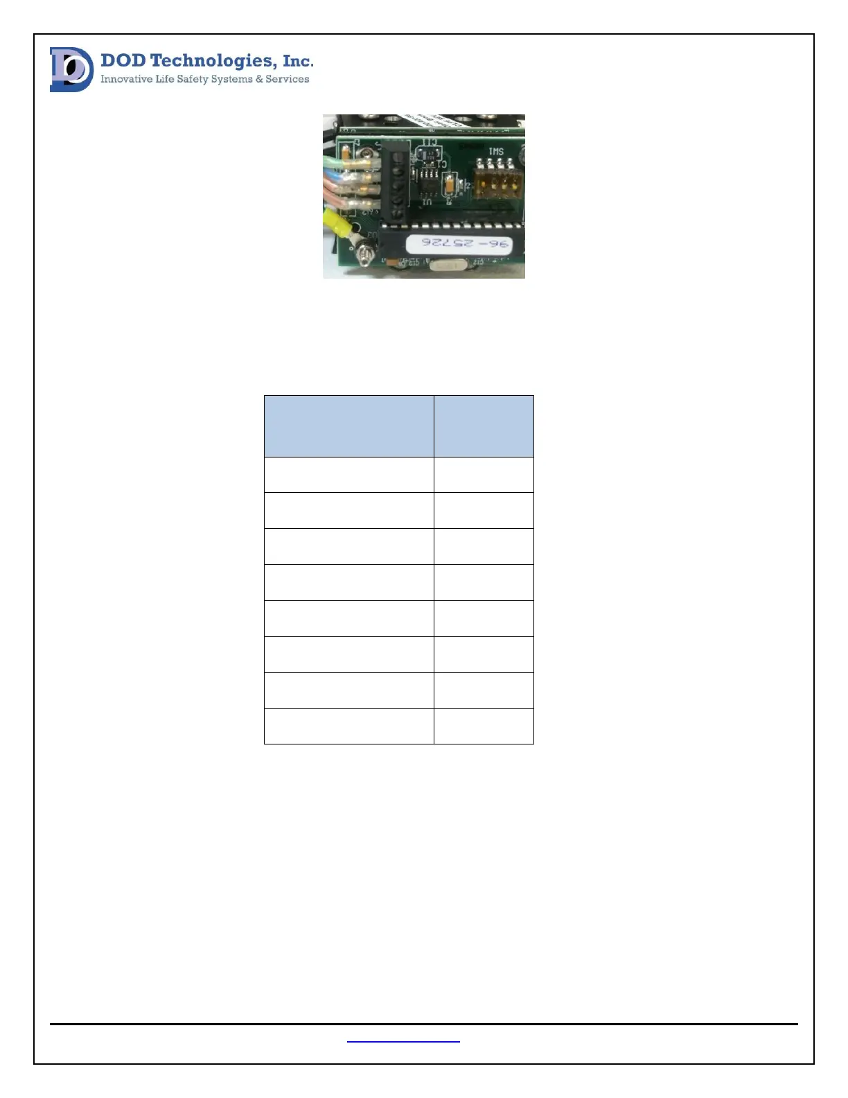
After the addresses are verified check to confirm the analyzer communication cable is connected
properly at the PC (see image below). Then confirm all optic block communication cables are securely
connected to the interconnect board below the analyzer (see image below).