G643(E) Service Manual Chapter 4. Engine Electrical System 113
Ignition System Control
Spark-ignited engines require accurate control of
spark timing and spark energy for efficient
combustion. The MI-07 ignition system provides this
control. The system consists of the following
components:
• SECM
• Distributer with ignition module *
• Ignition coil(s) *
• Crankshaft position sensor *
• Crankshaft timing wheel *
• Spark plugs *
(*) Customer-supplied components
The SECM, through use of embedded control
algorithms and calibration variables, determines the
proper time to start energizing the coil and fire the
spark plug. This requires accurate crank/camshaft
position information, an engine speed calculation,
coil energy information, and target spark timing. The
SECM provides a TTL compatible signal for spark
control. The coil must contain the driver circuitry
necessary to energize the primary spark coil
otherwise an intermediary coil driver device must be
provided. The SECM controls spark energy (dwell
time) and spark discharge timing.
Figure 14. GM Distributor
The MI-07 system is capable of operating with either
a distributor based ignition system or a
distributorless ignition system. The current
application uses a distributor based ignition system.
The distributor will have no internal advance
mechanisms giving the SECM consistent authority
over ignition timing. The spark is sent to the
appropriate cylinder in the conventional way via the
rotor arm and spark plug wires. The SECM uses the
signal from the GM (General Motors) Delco Ignition
Module to determine the engine position and RPM
at any time. It uses this information together with the
information from the TPS sensor and TMAP to
calculate the appropriate ignition timing settings.
The General Motors (GM) distributor (Figure 14)
used in the Delco EST ignition system, incorporates
a Variable Reluctance (VR) sensor, which transmits
a reference signal to the GM ignition module (Figure
15) located on the distributor. A variable reluctance
sensor is an electromagnetic device consisting of a
permanent magnet surrounded by a winding of wire.
The sensor is used in conjunction with a ferrous
signal rotor on the distributor shaft. The signal rotor
has six lobes, one for each cylinder. Rotation of the
signal rotor near the tip of the sensor changes the
magnetic flux, creating an analog voltage signal in
the sensor coil.
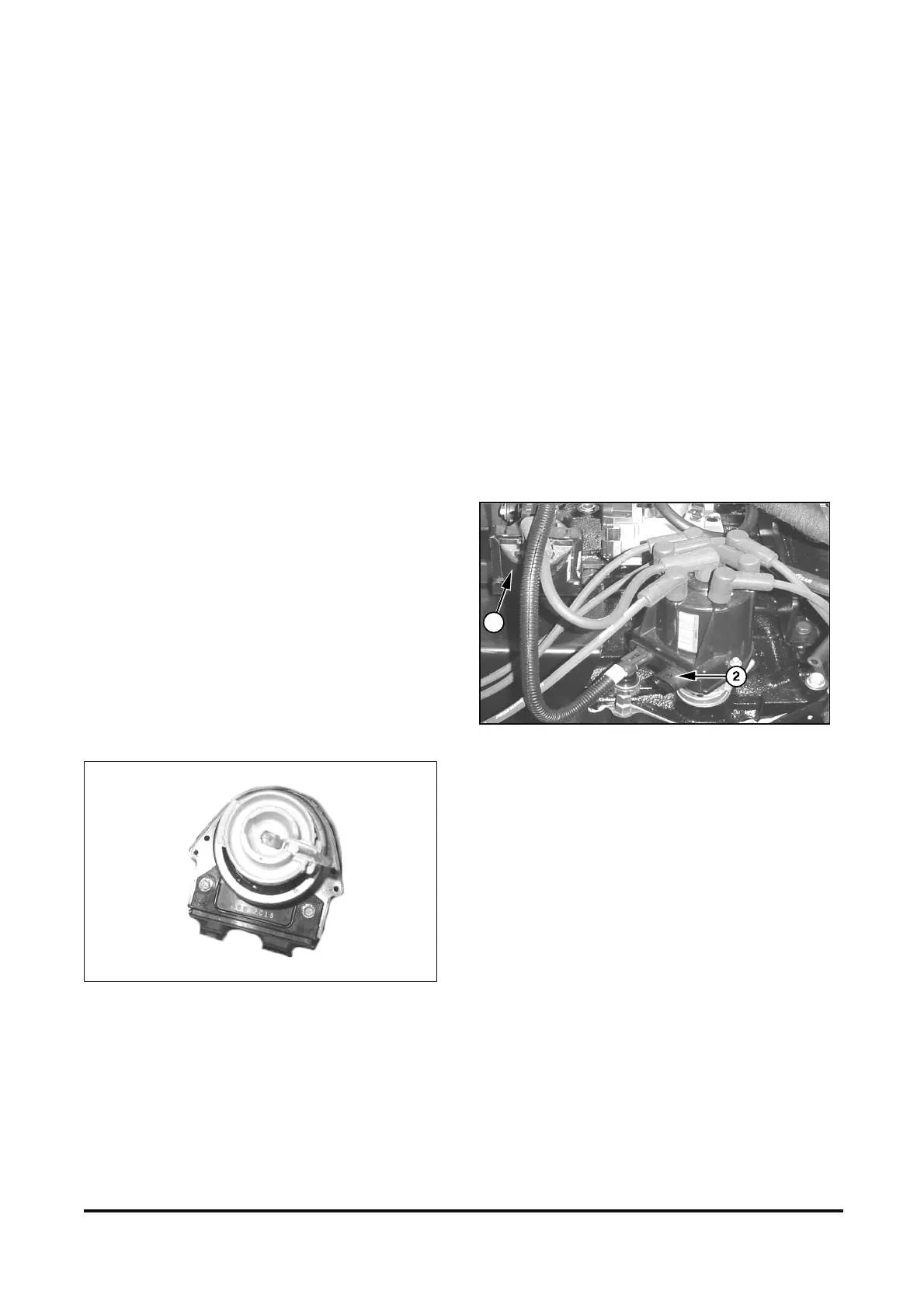
(1) lgnition Coil. (2) lgnition Module.
Figure 15. GM Ignition Module
The rising edge of the VR signal is converted to a
rising 5-volt signal by the ignition module. As the VR
signal passes back through zero volts, a falling edge
is created producing a square wave or digital signal,
similar to the signal produced by a Hall effect sensor.
This falling edge signal provides a stable engine
position reference at all engine speeds for the
SECM.
1