G643(E) Service Manual Chapter 5. Engine Management System (EMS) 165
Figure 21. Peak Torque and Power Available with
MI-07 System
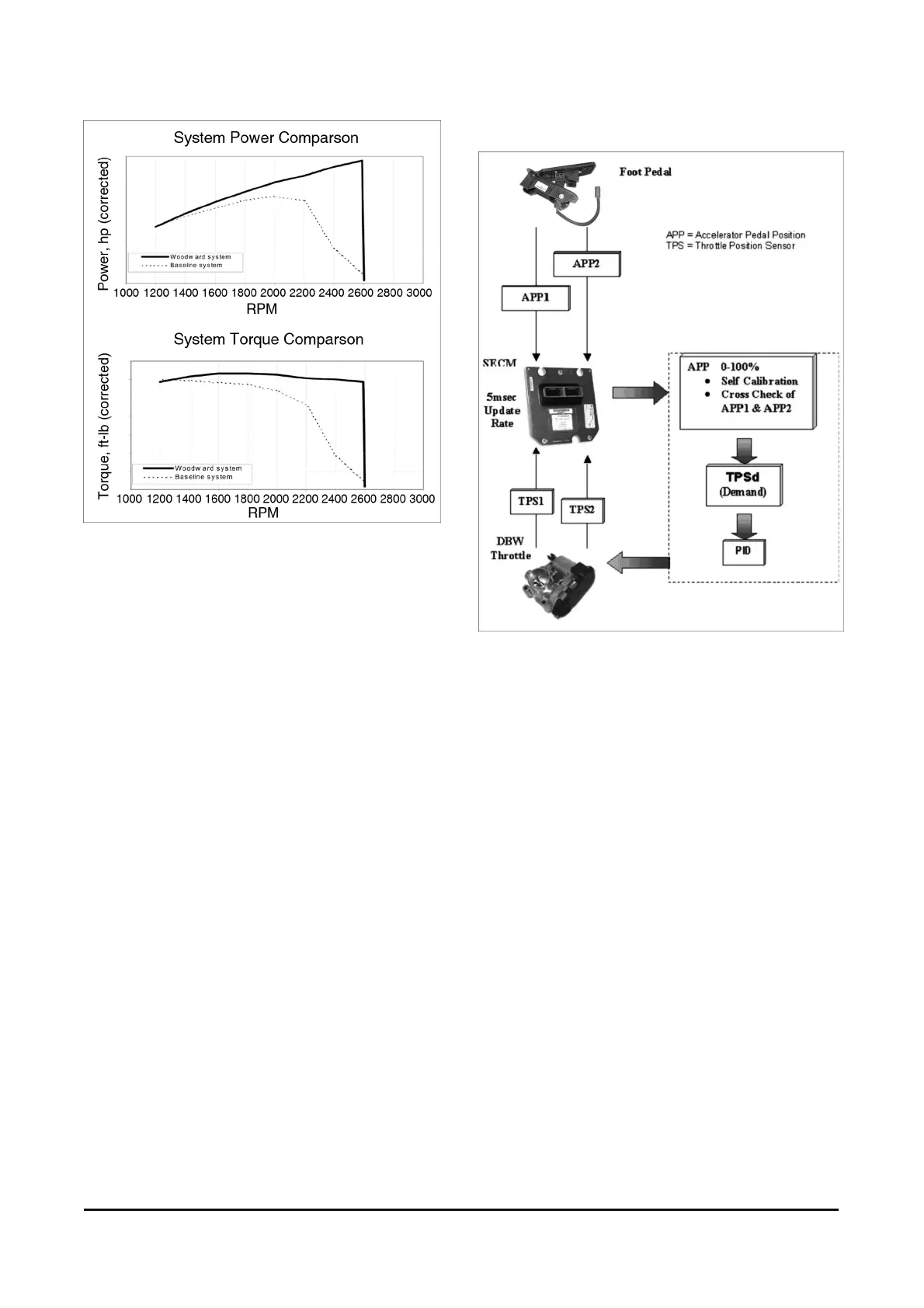
Drive-By-Wire Signal Flow Process
Figure 22. Drive-By-Wire Signal Flow Process
Figure 22 describes the signal flow process of the
MI-07 DBW section. The foot pedal assembly uses
two potentiometers to detect pedal position.
These two signals, accelerator pedal position 1
(APP1) and accelerator pedal position 2 (APP2) are
sent directly to the SECM.
The SECM uses a series of algorithms to self
calibrate and cross check the signals from the pedal
assembly. A demand position for the throttle will
then be derived and sent to the throttle as a throttle
position sensor demand (TPSd). This signal will be
processed through a PID (Proportional, Integral,
Derivative) controller in the SECM to achieve the
appropriate motor-current response then passed to
the throttle. The throttle moves to the commanded
position and provides a feedback signal from the
throttle position sensors (TPS1 and TPS2) to the
SECM.