Probe Installation and Wiring Procedure
1. Feed the blue probe cable through the bushing in riser cap.
2. Attach the cable connector to the socket in the probe head.
3. Carefully lower the probe into the riser pipe until it rests on the bottom of the tank. Be careful not to
damage the floats.
4. Tighten the riser cap bushing, leaving enough cable to reach the junction box.
5. Snap the riser cap in place. Secure the cap with a lock.
6. Install a 13 mm (0.5 in) NPT bushing into the junction box.
7. Pass the probe cable through this bushing into the box, and then tighten the bushing.
8. Pull the shielded cable through the rigid conduit and through the installed seal-offs at both ends of the
conduit run. Leave slack in the probe wiring emerging from the ends.
9. Using the silicon-filled wire nuts included with the probe, connect the blue probe cable to the shielded
cable inside the electrical junction box.
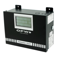
10. Remove the clear plastic cover located over the I.S. Interface Modules inside the SiteSentinel iTouch
Controller to attach the wiring from the probe conduit.
11. Connect the braided SHIELD from the Belden cable to the I.S. Module GROUND position.
12. Connect the BLACK wire to the I.S. Module SIGNAL position.
13. Connect the RED wire to the I.S. Module POWER position.
NOTE: When attaching probes to the Controller, start with I.S. Module Position “1” and work toward “16”. Fill
one strip before starting another.
Write down which probe goes to each position. You will need this when you configure the SiteSentinel ITouch
using the SiteConnect software.

 Loading...