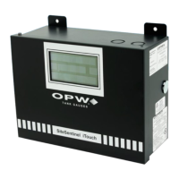
SiteSentinel iTouch Controller Setup for Interstitial (“I.S.”) Hydrocarbon Liquid/Water
Sensor
11.1.2 1st I.S. Module Position – Hydrocarbon Liquid
1. Configure the barrier position to be a generic sensor (or, if using SiteConnect choose the appropriate
icon) and install that position.
2. Using the Controller, take a dynamic reading of the hydrocarbon portion of the sensor.
3. Set the lower alarm threshold to be 0.5 volts lower than the reading taken (this assumes that there is
no current hydrocarbon contamination).
NOTE: SiteConnect will ask to adjust the lower threshold automatically, to 0.1 V below the current voltage
reading. Answer YES.
1. Set the upper alarm threshold to 5.0 volts (disables upper threshold).
2. Program the alarms associated with the lower threshold that you wish to activate if the sensor detects
hydrocarbon liquid.
11.1.3 2nd I.S. Module Position – Water
1. Configure the barrier position to be a generic sensor (or, if using SiteConnect choose the appropriate
icon) and install that position. Set the upper alarm threshold to 0.5 volts.
2. Set the lower alarm threshold 0 volts (disables lower threshold).
3. Set the lower alarm threshold to 0 volts (disables lower threshold).
4. Program the alarms associated with the upper threshold that you wish to activate if the sensor detects
water.
1.1.1 Testing and Decontaminating the Interstitial Hydrocarbon Liquid/Water Sensor
To prevent the possibility of explosion or fire, do not test the sensor in the
Hazardous Area.
Work in a well-ventilated area with no hot surfaces or open flames.
Do not use fuel to test the sensor!
If the SiteSentinel iTouch Controller fails to detect alarm conditions simulated here, also check that your
Controller thresholds are correct.
• Testing the Hydrocarbon Liquid Sensor Portion. Immerse the polymer in mineral spirits for about
10 minutes> Remove the sensor and let it hang to air dry. After another 10 minutes any Controller
alarms or events associated with the hydrocarbon sensor should trigger. Disconnect this portion of the
sensor from the Controller – an alarm should result. Short across these Controller positions – an alarm
should also occur. If the open lead and/or short lead test fail, check all wiring and junction boxes for
continuity.
• Testing the Water Sensor Portion. Testing the Water Sensor Portion. Immerse just the end of the
sensor in tap water. Controller alarms or events associated with the water portion of the sensor should
trigger. Short the water portion of the sensor – an alarm should occur. If the short lead test fails, check
all wiring and junction boxes for continuity.

 Loading...