54 16.50 PRO DR
®
RAPID-FEED™ CHIPPER
N
• Wire Cutter/Stripper
Two 9/16" Wrenches
le Wrench
Instal
1. Insert a jack-stand or blocks at the front of the Chipper
itch off the ground.
Remove the Bolt and Loc
the Hitch Clip and Pin and remove the
4. Position the
th i ure 55).
ame and Tow
Hitch with two 3/4" wrenches.
Install
NOTE g
Tow Hitch ize
the Chipper for the next procedure. The Tow Bar must be in the
Horizo l
in the o
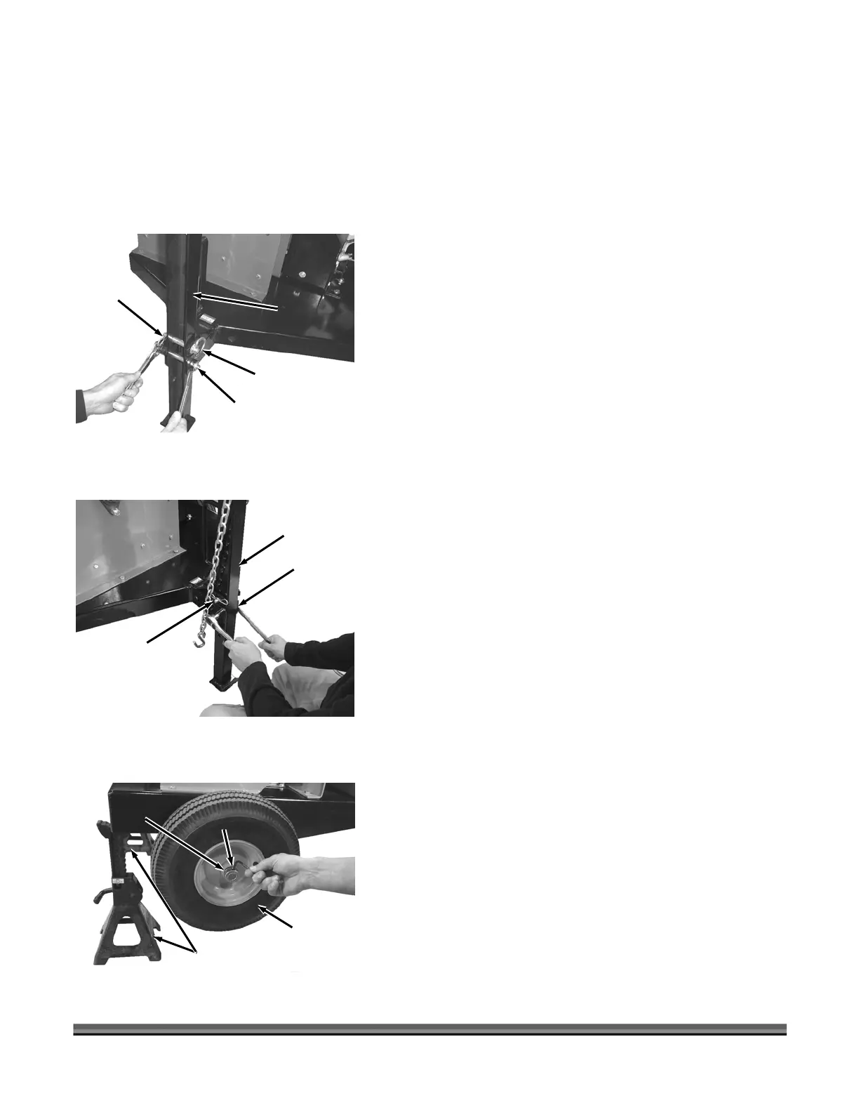
1. under the front corners of
2. p the rear of the Chipper and insert Jack Stands
under the rear corners of the Frame to raise the
Chipper wheels off the ground (Figure 56). The
lowermost part of frame must be at least 10" from the
ground for the Wheel Assembly to fit under.
INSTALLATIO
Tools and Supplies Needed:
• Cable Ties (provided)
• Two 3/4" Wrenches
•
Hitch C
Bolt and
ut Lockn
Roa
Tow Hi
d Towing
tch
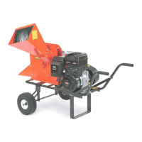
Bolt and
Locknut
Figure 54
Hitch
Clip
Pin
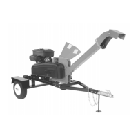
Standard
Tow Hitch
and Pin
Figure 55
lip
• Two 1/2" Wrenches
• 10" Adjustab
• Electrical Tape
• Jack Stands or Blocks
• Jack
• 5/32" Allen Wrench
• Needle Nose Pliers
• Hammer
ling the Tow Hitch:
to lift the Standard Tow H
2. knut from the Frame and
Standard Tow Hitch with two 3/4" wrenches (Figure
54).
3. Remove
Standard Tow Hitch.
Road-Towing Tow Hitch and secure with
e P n and Hitch Clip (Fig
5. Install the Bolt and Locknut into the Fr
ing the Fenders and Axle Assembly:
: It is recommended that the Ball Hitch on the Road-Towin
be hooked up to the Ball on your tow vehicle to stabil
nta position to hitch to the vehicle (see “Towing” procedures
foll wing section for Tow Bar adjustments).
Insert jack Stands or Blocks
Collar
Figure 56
Set Screw
Frame
Jack
Stands
Wheel and
Spacer (behind
wheel)
the Frame or hook the Ball Hitch onto the Ball of the
tow vehicle.
Jack u
 Loading...