5664.500/800 Evita 4/Evita 2 dura 06/98 Repair Instructions Page 6
For internal use only. Copyright reserved.
GBR5664500T055664800.fm 18.03.99
Dräger Medizintechnik
D
Repair Instructions – Electronic Components
1 Power Supply Unit
1.1 Output Voltages
The power supply unit provides the following output voltages:
•+24 V
•+15 V
•–15 V
•+12 V
•+5 V.
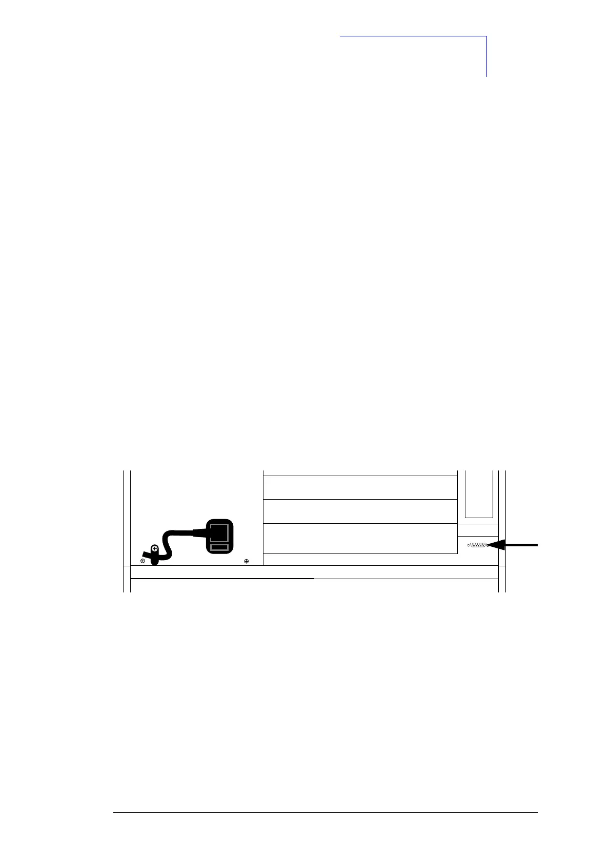
The output voltages and other signals are available at a Sub D socket (Extensionbox). This
Sub D socket is located on the rear panel.
Important: With devices manufactured end of 96 or later, the extension box connector is no
longer available. The voltages must therefore be measured on the Pneumatics Controller
PCB at pins X3, X11, and X21.
Fig. 1: Rear view (Sub D socket)
Extensionbox

 Loading...