24 Instructions for use | Dräger PointGard 2000 Series
en | Interface settings
DIP switch default settings for amber/red strobe
combination
DIP switch default settings for green/red strobe
combination
12.1.1 Setting the DIP switch pins
1. Open the instrument.
2. Toggle the DIP switch pins:
3. Close the instrument.
4. Commission the instrument.
13 Interface settings
13.1 4-20mA interface
The current output of the instrument during normal operation
is between 4 and 20 mA and is proportional to the detected
gas concentration.
PointGard 2xx0 uses different current values to indicate
various modes of operation. The factory default settings are
user adjustable for application specific requirements. This
follows the NAMUR recommendation NE43.
13.1.1 Full scale deflection
PointGard 2100 EC, 27x0 IR and 2200 CAT Remote LC only
Some sensors offer an adjustable full scale deflection to limit
the measuring range for the 4-20 mA interface.
The full scale deflection (FSD) sets an endpoint within the
measuring range of the sensor. If the gas concentration
reaches this endpoint, the 4-20mA interface transmits 20mA.
Example: Required range 0 to 500 ppm CO (e.g. part number
6809605 default 300 ppm, range min/max = 50/1000
ppm).Select full scale deflection as 500 ppm. The analog
output will be linear between 4 mA = 0 ppm and 20 mA = 500
ppm.
13.1.2 Setting fault current
This function defines the current for the fault signal.
1. Select Settings > Communication > Analog interface
>Fault current and confirm.
2. Select the line for editing the current and confirm.
3. Set the current and confirm.
The setting for the Fault current is displayed.
4. Select Confirm and confirm with [OK].
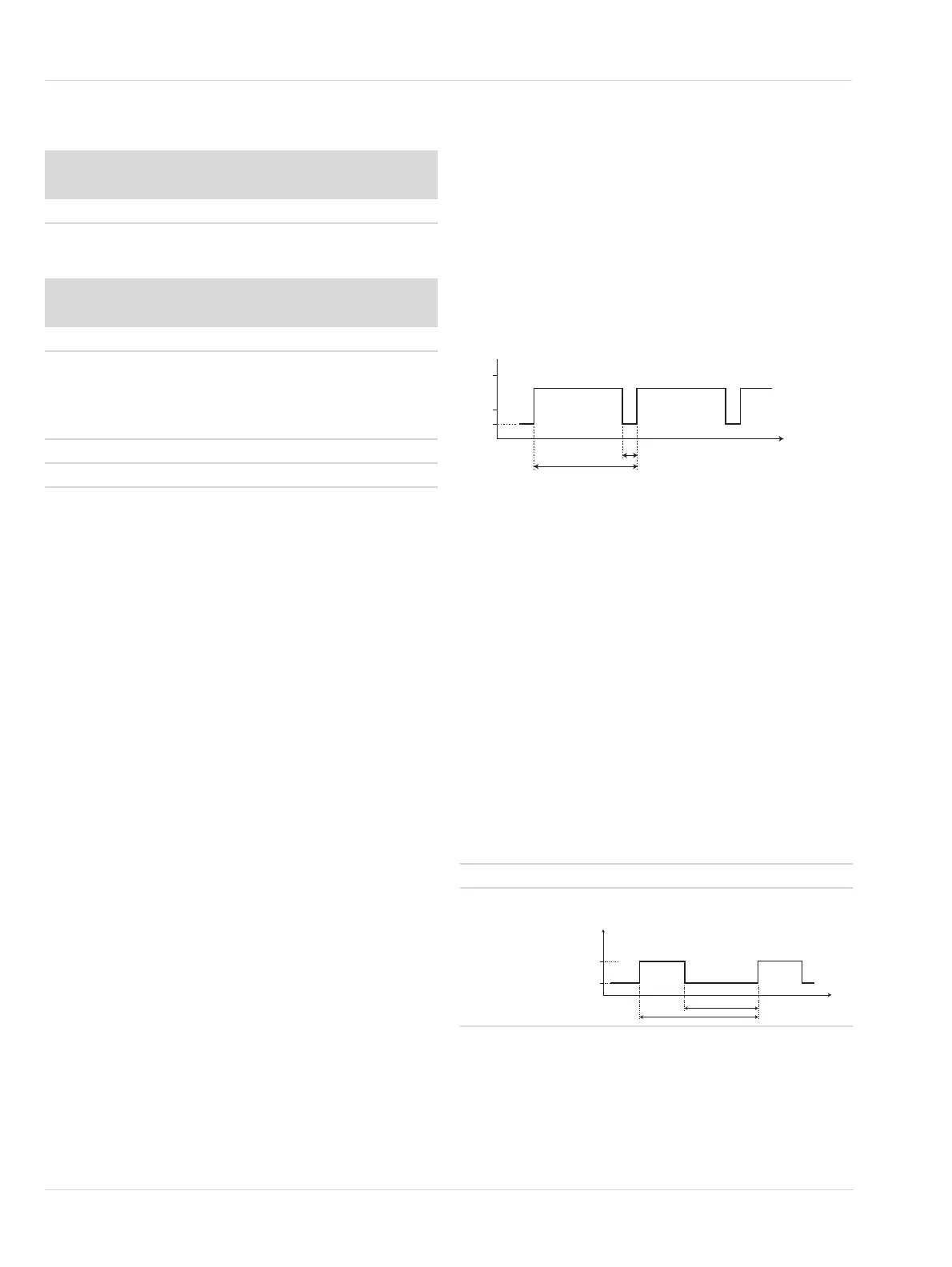
13.1.3 Information regarding the warning signal
To transmit a warning signal via the analog interface, the
warning signal must be switched on.
The warning signal alternates between the warning current
and the measurement current.
– Warning current (interval T2)
– Measurement current (interval T1-T2)
Time intervals and the warning current are configurable.
13.1.4 Switching the warning signal on or off
1. Select Settings > Communication > Analog interface >
Warning and confirm.
2. Select Enable or Disable and confirm.
13.1.5 Setting warning interval
1. Select Settings > Communication > Analog interface >
Warning interval and confirm.
2. Set times for warning intervals T1 and T2 and confirm.
13.1.6 Setting warning current
1. Select Settings > Communication > Analog interface >
Warning current and confirm.
2. Set the current and confirm with [OK].
13.1.7 Setting maintenance signal
1. Select Settings > Communication > Analog interface >
Maint. signal and confirm.
2. Set the signal type and confirm.
13.1.8 Setting static maintenance current
The maintenance current can only be set if the maintenance
signal has been set to static.
1. Select Settings > Communication > Analog interface
>Maint. current and confirm.
Pins
1 2 3 4 5
ON OFF OFF ON OFF
Pins
1 2 3 4 5
ON OFF ON ON OFF
to the left ON
to the right OFF
35869
static A constant current that can be configured.
dynamic A square wave signal with the following
characteristics:
t
[s]
T
1
4
20
[mA]
T
2
3
t
[s]
1,1
[mA]
0,7
5
3

 Loading...


