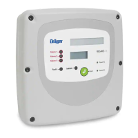
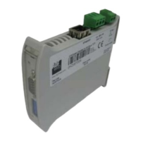
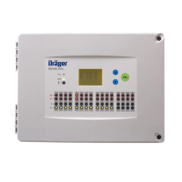
REGARD 8-Input 4-20 Module & 8-Channel Display Card (ATEX Version)
Issue 2. October 2011
20
Cmd. Command Function Command mode level Default
No. Name
Read Maint. Config.
Setting
00–0 CMD QUIT Quit command mode
• • •
00–1 PASSWORD Enter password
• • •
00–2 SAVE Save settings
• •
00–3 CHG P.WD Change password
• •
04–0 GAS NAME Set gas name
o o
•
CH4
04–1 UNITS Set gas units
o o
•
%LEL
04–2 FSD Set FSD (range)
o o
•
100
04–3 FSD LOCK Set over-range latching
o
•
YES
04–4 A1 ENER. Set relays normally energised or
o
•
ON ALARM
04–5 A2 ENER. energise on alarm
o
•
ON ALARM
10-0 SET ZERO Set zero
o
•
10-1 SET SPAN Set span
o
•
10–2 DRIFT Set zero drift band
•
0.0%
10–7 FLT U/R Set under-range fault level
o o
•
2.0
10–8 FLT O/R Set over-range fault level
o o
•
OFF
11–0 HYST Set alarm hysteresis
•
1.0%
11–1 A1 TRIP Set A1 alarm level
o o
•
20
11–2 A2 TRIP Set A2 alarm level
o o
•
40
11–4 A1 MODE Set A1 rising/falling
o o
•
RISE
11–5 A2 MODE Set A2 rising/falling
o o
•
RISE
11–7 A1 LATCH Set relays latching, non-latching,
o
•
DNAK
11–8 A2 LATCH delay-latching, acknowledgeable,
o
•
DNAK
11–9 F LATCH non-acknowledgeable
o
•
DNAK
14–0 LED TEST Test display & LEDs
• • •
14–1 RMT TEST Test remote reset
• • •
14–4 A1 TEST Test A1 relay
• •
14–5 A2 TEST Test A2 relay
• •
14–6 F TEST Test Fault relay
• •
14–8 TEST MOD Test input module communications
• •
52–0 HEADs Set number of heads
o o
•
h1 – h8
52–1 CARDs Set channel numbers
o o
•
Ch0
52–4 USER Set user definable text
•
????
52–6 CHECKSUM Set communications checksum
•
CRC
60–0 CMD LOCK Lock card in command mode
• •
NO
60–1 DISPLAY Gas level display on / off
•
ON
60–2 LEDs Set function of LEDs
o o
•
COMMON
60–3 HEAD NUM Display head or channel number
o o
•
HEAD h_
60–4 A1 DIS. Disable A1 relay
• •
NO
60–5 A2 DIS. Disable A2 relay
• •
NO
Key:
• Command available at this level, and setting can be changed
o Command available at this level, but setting cannot be changed