1-8
4400 Controls, Indicators, and Connectors, continued
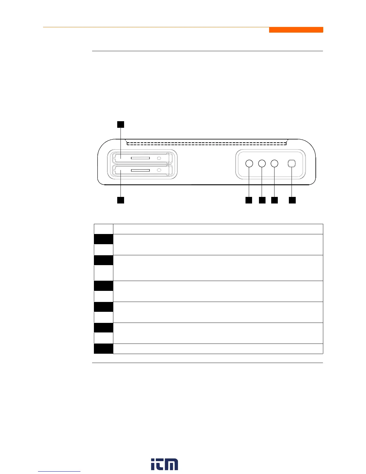
Bottom view
The bottom view features two slots. Either slot can be used to hold the data card.
NOTE: Use only one card slot (one data card) at a time. The additional slot will be used
for future communications options.
The bottom also features LED indicators and the On/Off power button. See below for
descriptions of the slots, indicators, and button.
Parts table
Part Function
1 Slot 1. Holds and connects data card to internal circuitry. Data card works in
either Slot 1 or Slot 2. Eject data card by pushing data card release.
2 Slot 2. Holds and connects data card to internal circuitry. Data card works in
either Slot 1 or Slot 2. Eject data card by pushing data card release.
NOTE: This additional slot will be used for future options.
3 Battery Charge Indicator. LED will light steadily while battery is fast
charging and blink when fully charged.
4 Status Indicator. LED will light steadily when abnormal condition is detected.
The unit is operating normally when light is off.
5 Power Indicator. LED will blink in a heartbeat fashion (once per second) when
the unit is operating normally.
6 On/Off Power Button. Push for on, push for off.
1
2 3 5 64
SLOT 1
SLOT 2
w ww . . co m
information@itm.com1.800.561.8187