EasyManuals Logo

Dranetz PowerGuide 4400 User Manual

Dranetz PowerGuide 4400
277 pages
To Next Page IconTo Next Page
To Previous Page IconTo Previous Page
Page #241 background imageLoading...
Page #241 background image
E-13
APPENDIX E/ Common Circuit Connections
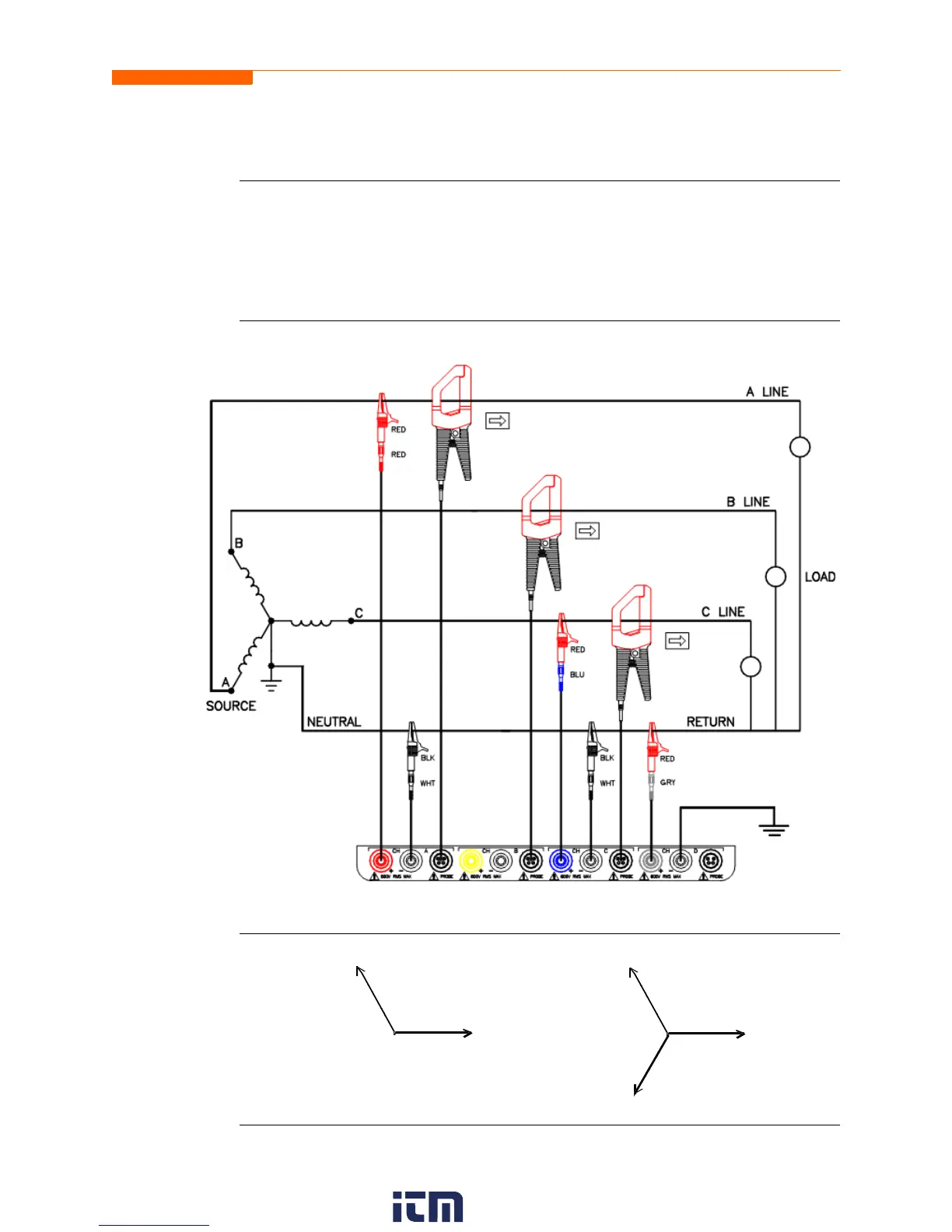
2 1/2 Element Without Voltage Channel B
Introduction
Channels A and C are connected to voltage. Current probes are connected to channels
A, B and C. The neutral is connected to common and is the reference for the three
channels. The figure also shows voltage connection using channel D as a differential
input for measuring neutral to ground voltage. Neutral to ground measurements are
important but optional.
Connection
diagram
Phasor
diagrams
PX5-907
V
A
120º
V
C
I
A
I
B
120º
I
C
240º
w ww . . co m
information@itm.com1.800.561.8187

Table of Contents

Questions and Answers:

Question and Answer IconNeed help?

Do you have a question about the Dranetz PowerGuide 4400 and is the answer not in the manual?

Dranetz PowerGuide 4400 Specifications

General IconGeneral
BrandDranetz
ModelPowerGuide 4400
CategoryMeasuring Instruments
LanguageEnglish

Related product manuals