2-6
Connecting Voltage Measurement Cables, continued
Connection
guidelines
Follow these guidelines when making voltage connections.
• Refer to the measurement cable set figure for color coding of probes that connect to
input channel connectors A, B, C, and D.
• Each channel input has plus (+) and minus (-) differential inputs of 1 to 600 Vrms
max.
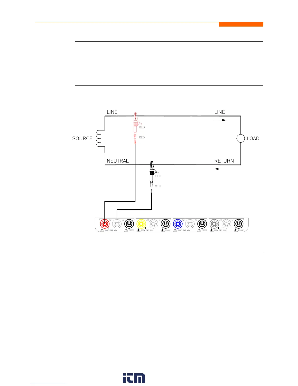
Example: Single
phase
connection
The following figure shows a voltage connection to a single phase circuit for channel A.
Continued on next page
PX5-12.vsd
w ww . . co m
information@itm.com1.800.561.8187