1BHFt%3*45&&.7BQPSMPHJD*OTUBMMBUJPOBOE0QFSBUJPO.BOVBM
4UFQo'JFMEXJSJOH
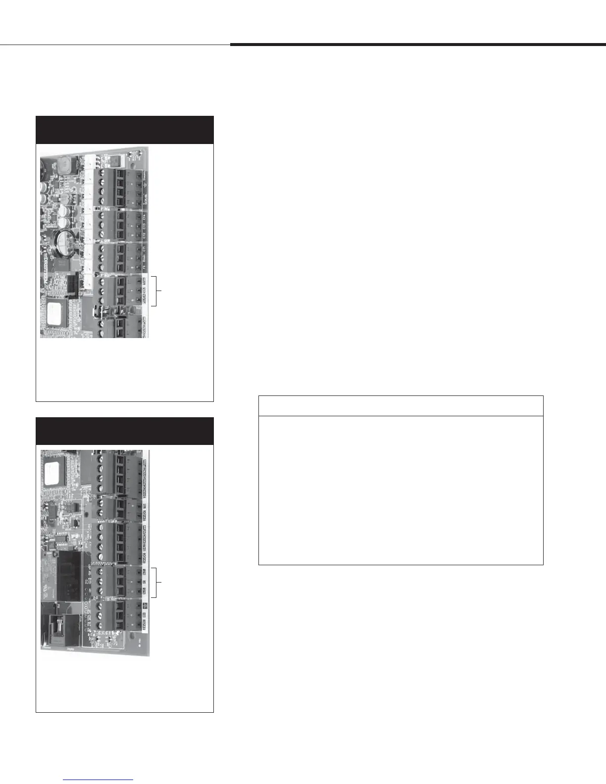
Programmable triac
See “Programmable triac maximum current” in Caution below.
Connect wiring to the output by inserting wires into the terminal
block plug at P16 (labeled Triac) and into the terminal block plug
at P19 (labeled ground), per the wiring diagram in Figure 25-1. This
connection allows remote activation of a device such as a fan or
signal light. Output parameters are defined during Step 2 of the
installation process.
Programmable relay (dry contact)
See “Programmable relay maximum current” in Caution below.
See Figure 25-1. Connect wiring for remote signaling using a
programmable relay (dry contact) by inserting wires into the
terminal block plug at P12 (labeled N.O., C, and N.C.), per the
wiring diagram in Figure 25-1. Tighten screws; maximum torque is 3
in-lb (0.34 N-m).
This connection allows remote activation of a device such as a fan
or signal light. Output parameters are defined during Step 2 of the
installation process.
Terminal P12
Figure 24-2:
Terminal P12
Terminal P12:
Programmable relay (dry contact) (10 AMP max. rated)
N.O. = Normally open
C = Common
N.C. = Normally closed
Terminal P16
Figure 24-1:
Terminal P16
Terminal P16: (all are triacs)
Triac = Programmable output (4 AMP max.)
(Note: Connect ground at P19)
PV/CA = Power vent/combustion air control signal
(24 VAC output)
SDU = Space Distribution Unit (24
VAC output)
Installation
CAUTION
Programmable triac maximum current
Programmable triac (P16) is rated for 100 mA from the factory, and
up to 4 Amps when a 24 VAC, 4 Amp (100 VA) transformer is wired
in parallel to the factory transformer. Exceeding this maximum
rating can cause the triac component or the Vapor-logic4 board to
fail.
Programmable relay maximum current
Programmable relay (dry contact) (P12) is rated for 24 VAC, 10 Amp
maximum. Exceeding this maximum rating can cause the relay
component or the Vapor-logic4 board to fail.
 Loading...