%3*45&&.7BQPSMPHJD*OTUBMMBUJPOBOE0QFSBUJPO.BOVBMt1BHF
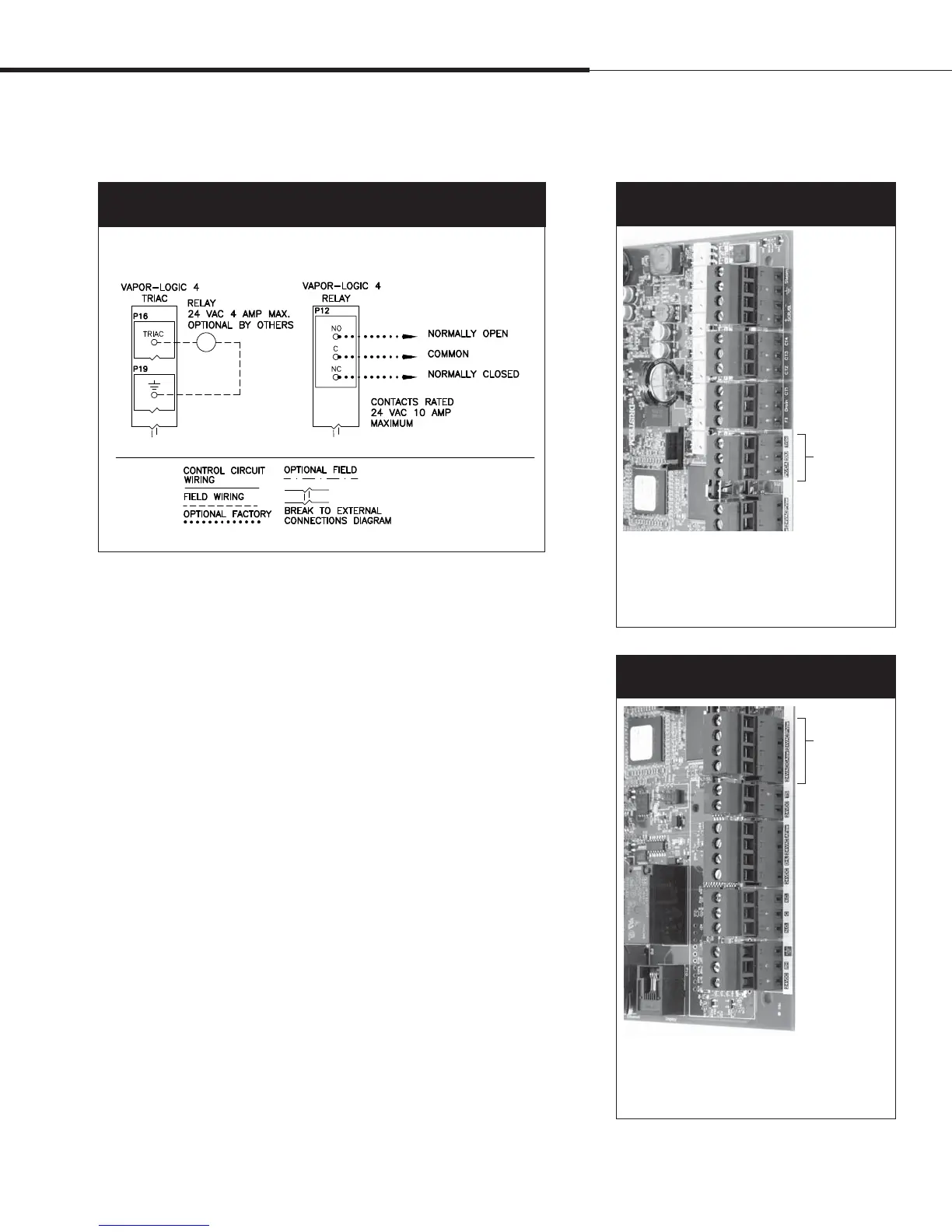
Figure 25-1:
Vapor-logic4 programmable triac and relay wiring connections
Programmable triac and relay
Key
Terminal P15
Figure 25-3:
Terminal P15
Terminal P15:
24VAC = Power to combustion air switch
CAsw = Combust. air sw. (24
VAC input)
24VAC = Power to power vent switch
PVsw = Power vent switch (24VAC input)
Terminal P16
Figure 25-2:
Terminal P16
Terminal P16: (all are triacs)
Triac = Programmable output
(Note: Connect ground at P19)
PV/CA = Power vent/combustion air control signal
(24 VAC output)
SDU = Space Distribution Unit (24
VAC output)
4UFQo'JFMEXJSJOH
Area-type and SDU dispersion fans
Connect wiring for Area-type and Space Distribution Unit (SDU)
dispersion fans by inserting the wire into the terminal block plug
at P16 (labeled SDU). Tighten screws; maximum torque is 3 in-lb
(0.34 N-m).
Optional combustion air switch and power vent (GTS systems)
Connect wiring for GTS combustion air switch and/or GTS power
vent by inserting wires into the terminal block plugs at P15 and
P16. Tighten screws; maximum torque is 3 in-lb (0.34 N-m).
The combustion air switch is on the combustion air damper. The
power vent switch indicates airflow at the power venter.
Installation
 Loading...