Copyright 2008 Baker Hughes Company.
4 | PACE5000/6000 Safety Instructions–English
3. +ve supply port.
4. -ve supply port.
5. Maximum Working Pressure (MWP).
6. Output port.
7. Vent port.
8. Reference port.
9. PACE5000
10. Control module.
11. PACE6000
12. Blanking plates.
1.1 Pressure Adaptors
Figure B1 shows the available range of PACE pressure adaptors. Refer to Table 1 and the Data
Sheet for more information.
1.2 Pressure Connection
The PACE has parallel thread pressure connectors. Use only the connector type specified in
Table 2.
Refer to Figure B2 for connection to the PA
CE pressure connectors and the key below:
1. PACE pressure connector.
2. Bonded seal.
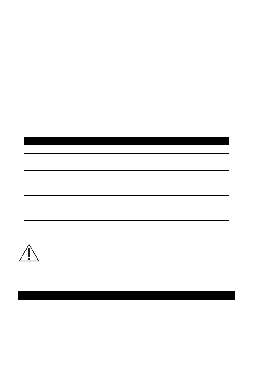
Table 1: P
ressure Adaptor Specification
Adaptor Part Number Specification
IO-SNUBBER-1 Restrictor/Snubber
IO-DIFFUSER-1 Diffuser
IO-ADAPT-1/4NPT ISO 228 G1/8 Male to 1/4 NPT Female.
IO-ADAPT-1/8NPT ISO 228 G1/8 Male to 1/8 NPT Female.
IO-ADAPT-7/16UNF ISO 228 G1/8 Male to 7/16-20 UNF Female.
IO-ADAPT-AN4 ISO 228 G1/8 Male to AN4 37° Male.
IO-ADAPT-AN6 ISO 228 G1/8 Male to AN6 37° Male.
IO-ADAPT-BARB ISO 228 G1/8 Male to 1/4 Hose.
IO-ADAPT-G1/4 ISO 228 G1/8 Male to ISO 228 G1/4 Female.
IO-ADAPT-G1/8 ISO 228 G1/8 Male to ISO 228 G1/8 Female.
WARNING Parallel threads must be used. Female thread type is parallel
thread to ISO228/1 (DIN ISO228/1, JIS B0202) G1/8.
Tapered threads not allowed.
Table 2: PACE Pressure Connector Thread Specification
PACE Connector Thread Specification
Supply +, Supply -, Output, Vent,
Reference
ISO228/1 G1/8 Parallel Threads (DIN ISO228/1, JIS B0202)

 Loading...