Copyright 2008 Baker Hughes Company.
English–PACE5000/6000 Safety Instructions | 9
Note: Refer to the PACE User Manual, Reference and Specification for details of other system
components.
3. Operation
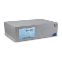
After the power-up sequence, the instrument shows the default display on the touch screen. The
touch screen divides into a number of mimic keys.
3.1 PACE5000 Single Chanel Display
Refer to Figure D1 and the key below:
1. Status
2. Switches between measure and control modes
3. Enter new set-point value
4. Controller set-up menu
5. Measure mode set-up menu
3.2 PACE6000 Single Chanel Display
Refer to Figure D2 and the key below:
1. Status
2. Switches between measure and control modes
3. Enter new set-point value
4. Controller set-up menu
5. Measure mode set-up menu
Note: The PACE6000 can be set to show a single channel display.
3.3 Setpoint Functional Description
Refer to Figure D3 and the key below:
1. Back space (deletes last entered character)
2. Switches positive/negative value
3. Enters decimal point
4. Escape - exits this menu
5. Selects new digit for set-point value
6. Accepts (enters) new complete set-point value
* High pressure gas exhaust - depending on pressure range.
** Optional vacuum system kit, allows the -ve port gas to be directly discharged to atmosphere, by-
passing the vacuum pump.
† Optimum controller transient response and minimum time to set-point may be degraded if either the
pneumatic supply or vacuum system has restricted flow. Installing a reservoir volume, which has larger
capacity than the load volume, located in close proximity to the controller supply ports can improve the
controller response.
‡ Optional negative gauge pressure generator kit, allows the -ve port to directly discharge to
atmosphere, by-passing the negative gauge pressure generator.
To protect the control module, for ranges above 100 bar (1450 psi), from over-pressure a suitable
protection device (such as a relief valve or bursting disc) must be fitted to limit the applied supply
pressure to below the Maximum Working Pressure (MWP).
Optional differential connection kit.
 Loading...