24
[012] - Keypad Lockout Options
The panel can be programmed to ‘lockout’ keypads if a series of
incorrect access code entries are made. After the Number of
Invalid Codes Before Lockout has been reached the panel will
lock out the keypad for the Lockout Duration and log the event
to the event buffer. For the duration of the lockout the panel will
sound an error tone when any key is pressed. To program ‘Num-
ber of Invalid Codes Before Lockout’.
Enter a number from 000 to 255 to determine the number of
invalid master, duress, user or installer access code entries to
reach keypad lockout. When keypad lockout occurs, the system is
rendered inoperative via keypad for the programmed duration.
When any keys are pressed, an error tone will sound.
To program ‘Lockout Duration’, enter a time from 000 to 255 min-
utes to determine the length of time before lockout resets and the
keypad can once again be used.
To disable Keypad Lockout enter the Number of Invalid Codes
Before Lockout as (000).
NOTE:
If lockout is not reached within the hour roll-over, the
number of invalid attempts is reset to 0.
NOTE: FAP keys are still active during Keypad Lockout.
NOTE: Keypad Lockout is a Global Feature.
NOTE: If Keypad Lockout is active, the panel cannot be armed or
disarmed with a keyswitch.
[013] - First System Option Codes
29 Zone Follower Output This output type is normally active and allows an output to deactivate for the duration that a zone is violated. The PGM
Attributes are an eight-bit toggle mask that selects which zones the output will follow. Example: If PGM 1 is pro-
grammed as Type [29] with Attributes 1, 6, and 8 on, the Output will turn off when any one of Zones 1, 6, or 8 are in
violation, and will activate when all three zones are restored.
NOTE: The toggle mask always works as an OR function. If any zones are violated, the output turns off, and
will not activate until all outputs are restored.
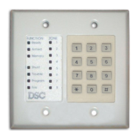
30 Partition Status Alarm
Memory Output
This feature is intended to be used on a keyswitch plate and will function as follows:
• This feature is partition dependant and is programmed in the PGM attributes.
• This output will activate (steady), at the beginning of the exit delay, when the partition is armed.
• If an alarm occurs on the armed partition, the output will flash (1 sec ON, 1 sec OFF) for the remainder of the armed
period
• If an alarm occurs on a disarmed partition (24 Hr zone), the output will flash (1 sec ON, 1 sec OFF) until the alarm is
acknowledged (bells are silenced during Bell Time Out, or the partition is armed after Bell Time Out).
• This output is type 30.
• This output will not activate in walk test.
31 Alternate Communicator This output will activate (switch to ground) when any of the selected system events (alarms) occur on the system. In the
armed state, the output will deactivate only once the system is disarmed. This output will activate when the pro-
grammed event occurs on any partition. If an alarm activates this output in the disarmed state, the output will deacti-
vate if a valid access code is entered within the bell cut-off time or if the system is armed after bell cut-off time has
expired. This output can be used to indicate that an alarm has occured before entering the premises. The PGM
attributes for this option, programmed in sections [501] to [514], differ from the standard selection of attributes nor-
mally programmed. Program the events that will activate the output by selecting some or all of the following attributes:
Bit [1] Fire (Fire Kes, Fire Zones)
Bit [2] Panic (Panic Keys and Panic Zones)
Bit [3] Burglary (Delay, Instant, Interior, Stay/Away and 24 hour Burglary Zones)
Bit [4] Opening/Closeing Events
Bit [5] Configured for Zone Omit. (Please see section “Automatic Bypass at End of Confirmation Window” on page 34
for details).
Bit [6] Medical (Auxiliary Keys, Medical and Emergency Zones)
Bit [7] Police Code Events Only
Bit [8] Output follows pulse timer (section [170] )
NOTE: This output will activate for silent and audible alarms or medical conditions only. It will not activate
during pre-alert or delays.
32 Open After Alarm This Programmable Output type activates for a 5 second period when the system has been disarmed after an alarm.
33 Bell Status and Program-
ming Access Output
This PGM output follows the Bell status as well as the Installer or DLS access. It activates when the Bell turns on and
turns off after BTO. It also activates when the panel is in Installer programming mode or the DLS is active and turns off
when the Installer mode exited or the DLS disconnected.
34 Away Armed with no
Zone Bypassed Status
This PGM output activates when the system is armed with the Stay/Away zones active and no zones bypassed.
Option Output Description
Option Definition On/Off Description
1 Zone Loop Type ON Normally Closed Loops All zones are wired as normally closed circuits with returns connected to a COM
terminal. The end-of-line resistor is not required. An alarm will be generated when the circuit is opened.
OFF End-of-Line Resistors All zones must be wired with an end-of-line resistor configuration, determined by
Option 2 in this system.
NOTE: The valid EOL value is 5600 Ohms (5.6KW).
2 End-of-Line Option ON Double End-of-Line Resistors All zones will use Double-End-of-Line resistors, except Standard Fire,
Delayed Fire, Supervisory, and LINKS Answer zone types. These zones must be connected using the EOL
resistor. Double EOL resistors enables detection of zone faults and tampers. The tamper resistor (5.6KΩ) is
placed across the alarm activating device, and the single EOL resistor (5.6KΩ) is placed between the alarm
and tamper contacts. This configuration will allow the panel to detect zone faults (zone shorted), zone
tampers (open zone), zone alarms (11.2KΩ), and restored zones (5.6KΩ).
If the zone is disarmed and placed in the tamper (open) or fault (short) state, trouble beeps will generate on
all system keypads until a key is pressed. A zone tamper will be sent to the monitoring station if pro-
grammed. If the zone is armed and a tamper is activated, The tamper alarm and zone alarm will be logged
and transmitted. The zone will begin normal alarm sequence (Alarm, Bell, etc.).